3.126
9928487 R01 - 2018 RANGER XP 1000 Service Manual
© Copyright Polaris Industries Inc.
HVAC CONTROL SERVICE
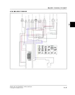
HVAC CONTROL OPERATION OVERVIEW
Power is supplied to the HVAC system through the 30
amp HVAC fuse located in the fuse / relay box under the
center console. The condenser fan is powered by a 20
amp circuit breaker through the Condenser Fan relay.
The HVAC relay is powered by the 30 Amp HVAC fuse.
When they key is in the ON position, the HVAC relay is
energized. Power is sent on the Red/Green wires to the
blower switch, the temperature knob (temp pot 10k) and
the water valve. Power only travels from the blower
switch to the AC switch on the white wire when the knob
is in the low, medium or high setting. If the AC switch is
ON, power is sent out on the blue wire to power the
condenser fan relay and the thermostat on the AC
evaporator. The evaporator thermostat will send power
on the white wire to the HPCO (high pressure cut-out)
switch located in the AC hose. The switch is normally
closed. When the switch is closed, power is sent to the
AC compressor. When the pressure in the AC line gets
too high, the switch opens and the compressor cycles
off. The condenser fan will always be running when the
AC system is on and it is powered by a 20 Amp circuit
breaker just outside the relay box.
As the temperature knob is moved towards the warm
setting,
the
voltage
through
the
potentiometer
is
interpreted by the water valve to control the flow of warm
water through the heater core to warm the air.
The HVAC control panel is a single unit. If any of the
individual switches are found to not be functioning
properly, the whole panel must be replaced.
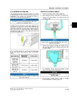
A/C SWITCH TESTING
The AC switch turns the Air Conditioning system on and
off.
The AC Switch can be tested using an ohmmeter.
1. Disconnect harness from AC Switch.
2. With the meter in the ohms mode, place the leads on
pins P1 and P3.
3. With the switch off, the reading should be OL.
4. With the switch on the reading should be less than 1
Ω.
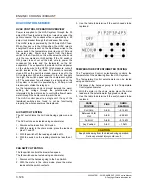
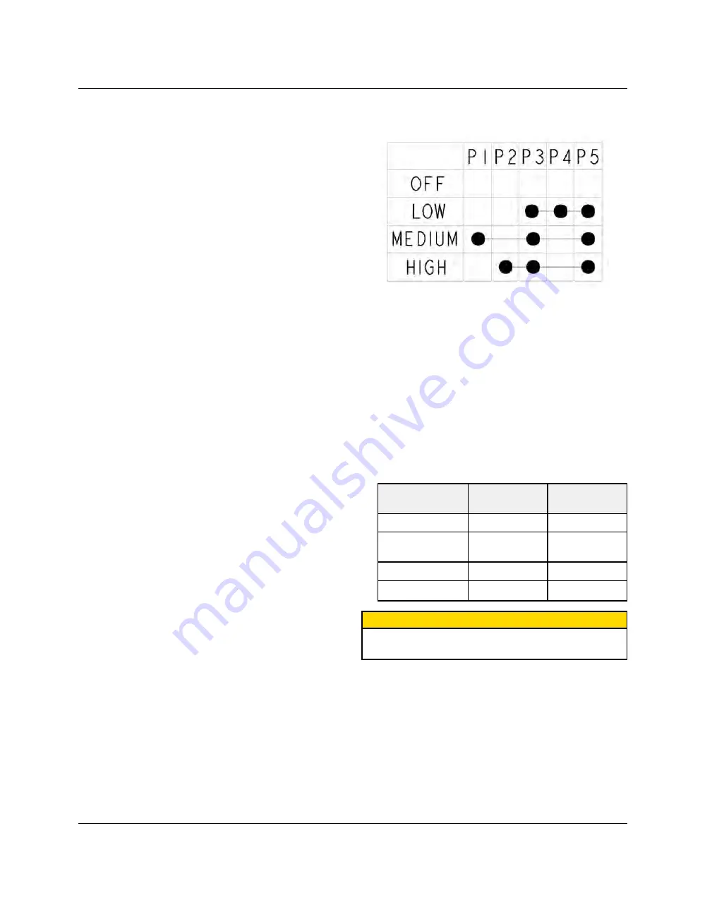
FAN SWITCH TESTING
The fan switch controls the blower fan speed.
The fan switch can be tested using an ohmmeter.
1. Disconnect the harness going to the Fan Switch.
2. With the meter in the ohms mode, place the meter
leads onto the switch contacts.
3. Use the table to determine if the switch needs to be
replaced.
TEMPERATURE POTENTIOMETER TESTING
The Temperature Control potentiometer controls the
temperature of the air blowing from the HVAC system.
The Temperature Control potentiometer can be tested
using an ohmmeter.
1. Disconnect the harness going to the Temperature
Control potentiometer.
2. With the meter in the ohms mode, place the meter
leads onto the potentiometer flying lead contacts.
3. Use the table to determine if the switch needs to be
replaced.
KNOB
POSITION
PINS
OHMS
READING
Full Cold
A to B
~ 81.5k Ω
Between Cold/
Hot
A to B
~ 86.5k Ω
Full Hot
A to B
~ 91.5k Ω
Any Position
A to C
~ 10k Ω
CAUTION
Keep hands away from fan blades during operation.
Serious personal injury could result.

