P/N 9926740 Rev 01 06/15 Page 4 of 12
CONTACTOR AND WIRING INSTALLATION
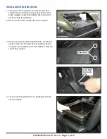
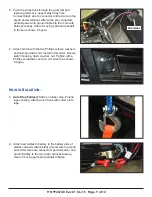
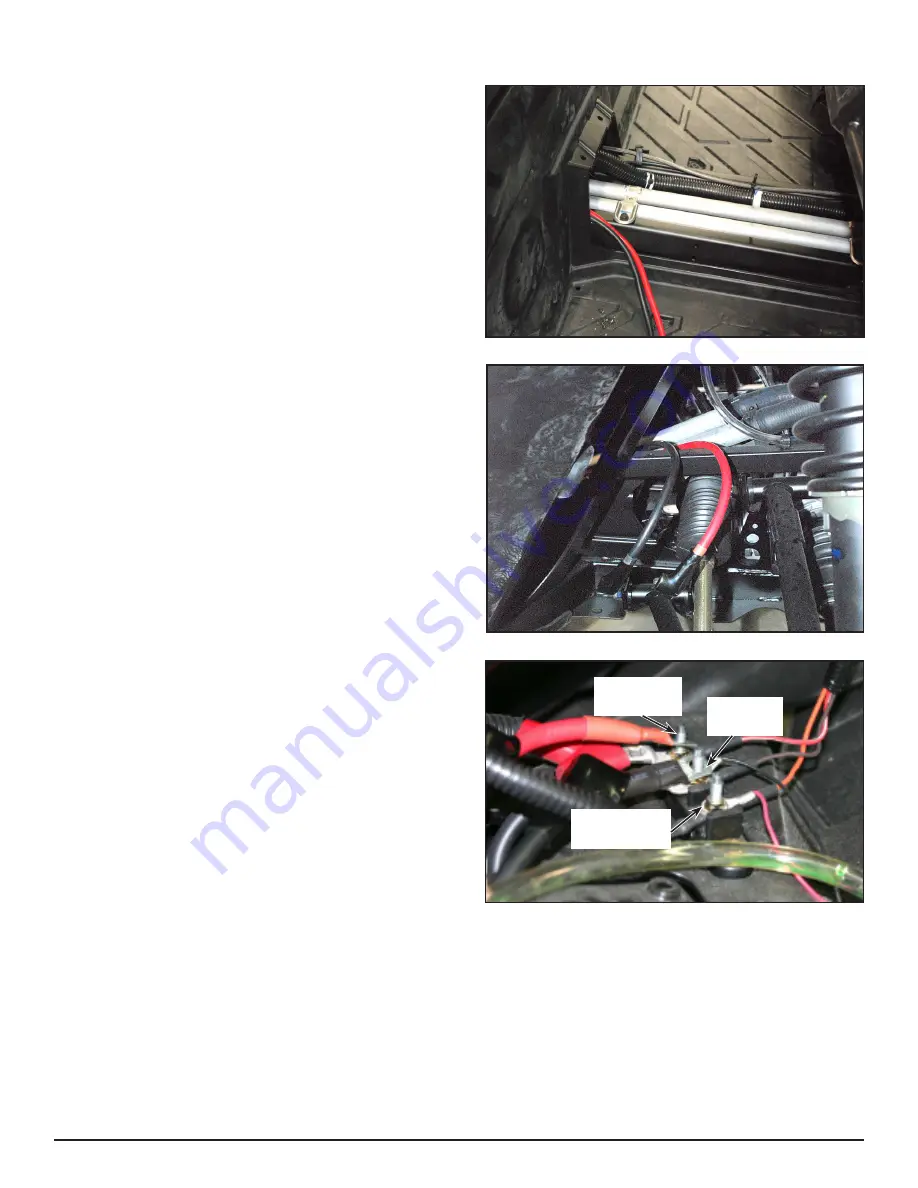
1. Install red and black power and ground cable (sold
separately, see Page 1) by sliding under seat where
center floor section was removed and route up to
battery by following the main wire harness. DO NOT
connect at this time as shown in figure.
On crew models, route hoses through the tunnel
area under the rear floor section and into the area
under the rear seat.
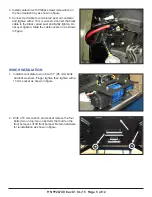
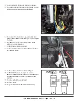
2. Slide the other end of cable through bulkhead.
Follow main wire harness up and onto the splash
tray as shown in figure.
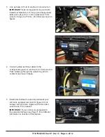
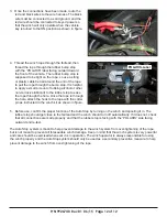
3. Connect short (250 mm) red and black cables to the
bus bar on the same posts as the wires previously
connected. Reinstall nuts on bus bar. Connect wires
to red and black terminals on contactor and lightly
tighten. DO NOT OVER TIGHTEN. Slide the cable
covers on as shown in figure.
Orange
(Key power)
Brown
(Ground)
Red/White
(B)


