ENGINE
3.58
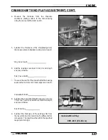
COUNTER BALANCER SHAFT END PLAY ADJUSTMENT
1.
Make sure all bearings are firmly seated in the
crankcase.
2.
Measure the width of the counter balancer shaft at
the bearing seats with a dial caliper or micrometer,
and record reading.
3.
Measure the distance from the Mag crankcase
mating surface to the balance shaft bearing using
a dial caliper and a straight edge. Subtract the
thickness of the straightedge and record.
4.
Measure the distance from the PTO crankcase
mating surface to the bearing using the same
method outlined in Step 1, 2, and-3.
5.
Add the readings obtained in Step 3 and Step 4.
6.
Subtract
the
counter
balancer
shaft
width
measured in step 2 from the figure obtained in step
5.
7.
Subtract the thickness of the existing shim from
the result of step 6 to determine if a different shim
is needed. The result must be within the specified
range listed at right.
Step 2
Step 3 / 4
Counter Balancer Shaft End Play:
.008
″
-.016
″
(.02-.04 cm)
Summary of Contents for Sportsman 400
Page 6: ...SPORTSMAN 400 A01CH42AC GENERAL INFORMATION 1 4 MODEL COLOR IDENTIFICATION ...
Page 21: ...Newton Meter to Pound Foot and Pound Inch GENERAL INFORMATION 1 19 TORQUE CONVERSIONS ...
Page 22: ...Newton Meter to Pound Foot and Pound Inch GENERAL INFORMATION 1 20 TORQUE CONVERSIONS ...
Page 152: ...Forward FUEL SYSTEM CARBURETION 4 2 FUEL TANK ASSEMBLY ...
Page 366: ...ELECTRONIC SPEEDOMETER WIRING DIAGRAM ELECTRICAL 10 32 ...
Page 372: ...ELECTRICAL 10 38 NOTES ...
Page 379: ...ELECTRICAL 10 39 WIRING DIAGRAM 2001 SPORTSMAN 400 ...
Page 380: ...ELECTRICAL 10 40 WIRING DIAGRAM 2001 SPORTSMAN 500 EARLY ...
Page 381: ...ELECTRICAL 10 41 WIRING DIAGRAM 2001 SPORTSMAN 500 LATE ...


