FINAL DRIVE
7.11
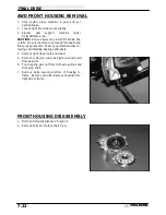
AWD FRONT DRIVE AXLE REMOVAL
1.
Loosen front wheel nuts slightly.
2.
Elevate and support machine under footrest/frame
area with front wheels elevated.
CAUTION: Serious injury may result if machine tips or
falls. Be sure machine is secure before beginning this
service procedure. Wear eye protection when remov-
ing and installing drive axles or component parts.
3.
Remove wheel nuts and wheels.
4.
Remove hub cap.
5.
Remove the two brake caliper attaching bolts.
CAUTION: Do not hang the caliper by the brake
hose.
Use wire to hang the caliper to prevent
possible damage to the brake line.
6.
Place a catch pan beneath the front hub and remove
the hub cap.
7.
Remove cotter pin and nut.
8.
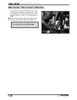
Remove hub, bearings, hilliard assembly, and
armature plate.
Summary of Contents for Sportsman 400
Page 6: ...SPORTSMAN 400 A01CH42AC GENERAL INFORMATION 1 4 MODEL COLOR IDENTIFICATION ...
Page 21: ...Newton Meter to Pound Foot and Pound Inch GENERAL INFORMATION 1 19 TORQUE CONVERSIONS ...
Page 22: ...Newton Meter to Pound Foot and Pound Inch GENERAL INFORMATION 1 20 TORQUE CONVERSIONS ...
Page 152: ...Forward FUEL SYSTEM CARBURETION 4 2 FUEL TANK ASSEMBLY ...
Page 366: ...ELECTRONIC SPEEDOMETER WIRING DIAGRAM ELECTRICAL 10 32 ...
Page 372: ...ELECTRICAL 10 38 NOTES ...
Page 379: ...ELECTRICAL 10 39 WIRING DIAGRAM 2001 SPORTSMAN 400 ...
Page 380: ...ELECTRICAL 10 40 WIRING DIAGRAM 2001 SPORTSMAN 500 EARLY ...
Page 381: ...ELECTRICAL 10 41 WIRING DIAGRAM 2001 SPORTSMAN 500 LATE ...


