FINAL DRIVE
7.24
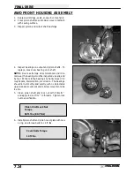
AWD FRONT HOUSING ASSEMBLY
1.
Replace all O-rings, seals, and worn components.
2.
Press pinion shaft seal into pinion cover until flush
with sealing surface.
3.
Inspect pinion and output shaft bushings.
4.
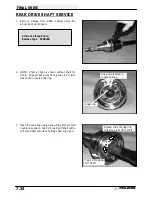
Inspect bearings on output and pinion shafts. To
replace, press new bearing on to shaft.
NOTE: Due to extremely close tolerances and mini-
mal wear, the bearings must be inspected visually, and
by feel. While rotating bearings by hand, inspect for
rough spots, discoloration, or corrosion. The bearings
should turn smoothly and quietly, with no detectable
up and down movement and minimal movement side
to side.
5.
Clean pinion shaft and lock nut with PrimerN
t
and apply red LocTite
t
to threads. Tighten lock
nut to specification.
6.
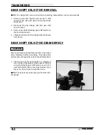
Install pinion shaft and pinion cover plate with new
o-ring and torque bolts to 14 ft. lbs.
Bushings
Pinion Shaft Lock Nut
Torque
65 ft. lbs. (89.7 Nm)
Cover Bolts Torque
14 ft. lbs.
Summary of Contents for Sportsman 400
Page 6: ...SPORTSMAN 400 A01CH42AC GENERAL INFORMATION 1 4 MODEL COLOR IDENTIFICATION ...
Page 21: ...Newton Meter to Pound Foot and Pound Inch GENERAL INFORMATION 1 19 TORQUE CONVERSIONS ...
Page 22: ...Newton Meter to Pound Foot and Pound Inch GENERAL INFORMATION 1 20 TORQUE CONVERSIONS ...
Page 152: ...Forward FUEL SYSTEM CARBURETION 4 2 FUEL TANK ASSEMBLY ...
Page 366: ...ELECTRONIC SPEEDOMETER WIRING DIAGRAM ELECTRICAL 10 32 ...
Page 372: ...ELECTRICAL 10 38 NOTES ...
Page 379: ...ELECTRICAL 10 39 WIRING DIAGRAM 2001 SPORTSMAN 400 ...
Page 380: ...ELECTRICAL 10 40 WIRING DIAGRAM 2001 SPORTSMAN 500 EARLY ...
Page 381: ...ELECTRICAL 10 41 WIRING DIAGRAM 2001 SPORTSMAN 500 LATE ...


