BRAKES
9.6
AUXILIARY BRAKE INSPECTION (HYDRAULIC)
Use the following procedure to inspect the auxiliary
(foot) brake system and bleed if necessary.
1.
First check foot brake effectiveness by applying a
50 lb. (approx.) downward force on the pedal. The
top of the pedal should be at least 1
″
(25.4mm)
above the surface of the footrest (see Ill. 1).
Free play of the brake pedal should be 1/8 - 1/4 inch (3.2 - 6.35 mm).
If freeplay is excessive, be sure master cylinder piston is returning to the fully extended position. If freeplay is
less than 1/8
″
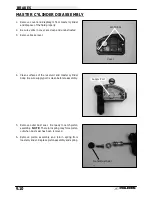
(3.2mm) be sure dust seal is fully seated in groove on master cylinder body. See photo on page
9.10.
Auxiliary Brake Testing
The auxiliary brake should be checked for proper adjust-
ment.
1. Support the rear wheels off the ground.
2. While turning the rear wheels by hand, apply the auxil-
iary foot brake. This brake should not stop the wheels
from turning until the lever is half way between its rest
position and bottoming on the footrest.
Bleeding:
If the free play is correct, but pedal travel is excessive or spongy, then air is trapped somewhere in the system.
Bleeding the auxiliary brake system is accomplished in a conventional manner, except that there are two brake
lines and bleeder screws on the Dual Hydraulic caliper. Refer to page 9.5 for theory of operation and bleeding
procedure. The auxiliary brake line applies pressure to the small (inner) diameter of the caliper piston. Use the
outermost (lower) bleed screw to purge air. See photo on page 9.5.
50 lbs
1
″
or greater
1/8
″
to 1/4
″
Free Play
Ill. 1
Floorboard
Auxiliary Foot Brake Pedal
Floor
Board Surface
Full Height
Engagement
(1/2 Height)
Full
Engagement
(Flush)
Summary of Contents for Sportsman 400
Page 6: ...SPORTSMAN 400 A01CH42AC GENERAL INFORMATION 1 4 MODEL COLOR IDENTIFICATION ...
Page 21: ...Newton Meter to Pound Foot and Pound Inch GENERAL INFORMATION 1 19 TORQUE CONVERSIONS ...
Page 22: ...Newton Meter to Pound Foot and Pound Inch GENERAL INFORMATION 1 20 TORQUE CONVERSIONS ...
Page 152: ...Forward FUEL SYSTEM CARBURETION 4 2 FUEL TANK ASSEMBLY ...
Page 366: ...ELECTRONIC SPEEDOMETER WIRING DIAGRAM ELECTRICAL 10 32 ...
Page 372: ...ELECTRICAL 10 38 NOTES ...
Page 379: ...ELECTRICAL 10 39 WIRING DIAGRAM 2001 SPORTSMAN 400 ...
Page 380: ...ELECTRICAL 10 40 WIRING DIAGRAM 2001 SPORTSMAN 500 EARLY ...
Page 381: ...ELECTRICAL 10 41 WIRING DIAGRAM 2001 SPORTSMAN 500 LATE ...


