ELECTRICAL
10.34
FAN CONTROL CIRCUIT OPERATION / TESTING
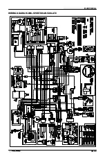
The fan switch is located on the radiator. Power is supplied to the fan switch via the Red/White wire when the
ignition key and auxiliary shut off switch are ON. When the fan switch reaches the specified temperature, it be-
comes conductive and sends power to the fan motor. The ground path for the fan motor is through the Brown
harness wire.
CAUTION: Keep hands away from fan blades during this procedure. Serious personal injury could result.
NOTE: The fan switch may not function or operation may be delayed if coolant level is low or if air is trapped in the
cooling system. Be sure cooling system is full and purged of air. Refer to Maintenance chapter 2.
FAN CONTROL SWITCH BYPASS TEST
1.
Disconnect harness from fan switch on radiator.
2.
Place a jumper wire between the wires in the connector.
3.
Turn ignition key (and engine stop switch) “ON”. The fan should start running.
4.
If the fan runs with the jumper wire installed, check the fan control switch and connector terminals. If the fan
does not run or runs slowly with the jumper wire installed, check the fan motor wiring, ground, and motor
condition (refer to Fan Motor Testing this section). Repair or replace as necessary.
FAN CONTROL SWITCH OPERATION TEST
1.
Place switch in a water bath and submerse it to the base of the threads. Do not allow threads to contact
container or inaccurate reading will result.
2.
Heat the coolant slowly and monitor the temperature with a thermometer or Fluke
t
meter pyrometer. The
switch should be closed (conductive) at the “ON” temperature indicated in the chart, and stay conductive until
the “OFF” temperature is reached.
REFER TO PARTS MANUAL FOR FAN SWITCH APPLICATION
Fan Switch Part Number
Continuity (On)
No Continuity (Off)
4010161
180
°
F (82
°
C)
±
3
°
F
149
°
F (65
°
C)
±
8
°
F
Summary of Contents for Sportsman 400
Page 6: ...SPORTSMAN 400 A01CH42AC GENERAL INFORMATION 1 4 MODEL COLOR IDENTIFICATION ...
Page 21: ...Newton Meter to Pound Foot and Pound Inch GENERAL INFORMATION 1 19 TORQUE CONVERSIONS ...
Page 22: ...Newton Meter to Pound Foot and Pound Inch GENERAL INFORMATION 1 20 TORQUE CONVERSIONS ...
Page 152: ...Forward FUEL SYSTEM CARBURETION 4 2 FUEL TANK ASSEMBLY ...
Page 366: ...ELECTRONIC SPEEDOMETER WIRING DIAGRAM ELECTRICAL 10 32 ...
Page 372: ...ELECTRICAL 10 38 NOTES ...
Page 379: ...ELECTRICAL 10 39 WIRING DIAGRAM 2001 SPORTSMAN 400 ...
Page 380: ...ELECTRICAL 10 40 WIRING DIAGRAM 2001 SPORTSMAN 500 EARLY ...
Page 381: ...ELECTRICAL 10 41 WIRING DIAGRAM 2001 SPORTSMAN 500 LATE ...

