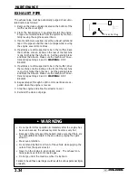
MAINTENANCE
2.22
COOLANT LEVEL INSPECTION
Therecoverybottle, locatedontheleft sideof themachine,
must be maintained between the minimum and maximum
levels indicated on the recovery bottle.
With the engine at operating temperature, the coolant level
should be between the upper and lower marks on the
coolant reservoir. If not:
1.
Remove reservoir cap. Inner splash cap vent hole
must be clear and open.
2.
Fill reservoir to upper mark with Polaris Premium
60/40 Anti Freeze / Coolant or 50/50 or 60/40 mixture
of antifreeze and distilled water as required for freeze
protection in your area.
3.
Reinstall cap.
NOTE: If overheating is evident, allow system to cool
completely and check coolant level in the radiator and in-
spect for signs of trapped air in system.
RADIATOR COOLANT LEVEL INSPECTION
NOTE: This procedure is only required if the cooling sys-
tem has been drained for maintenance and/or repair.
However, if the recovery bottle has run dry, or if overheat-
ing is evident, the level in the radiator should be inspected
and coolant added if necessary.
WARNING Never remove the pressure cap when
the engine is warm or hot. Escaping steam can cause se-
vere burns. The engine must be cool before removing the
pressure cap.
NOTE: Use of a non-standard pressure cap will not allow
the recovery system to function properly.
To access the radiator pressure cap:
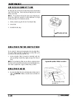
Remove the four screws securing front rack. Turn handle
bars full left or right to provide more clearance. Remove
front cover by placing your fingers under the front of the
cover and pulling upward.
Recovery
Bottle
Accessible
Under Side
Panel
Rack
Front
Cover
Summary of Contents for Sportsman 400
Page 6: ...SPORTSMAN 400 A01CH42AC GENERAL INFORMATION 1 4 MODEL COLOR IDENTIFICATION ...
Page 21: ...Newton Meter to Pound Foot and Pound Inch GENERAL INFORMATION 1 19 TORQUE CONVERSIONS ...
Page 22: ...Newton Meter to Pound Foot and Pound Inch GENERAL INFORMATION 1 20 TORQUE CONVERSIONS ...
Page 152: ...Forward FUEL SYSTEM CARBURETION 4 2 FUEL TANK ASSEMBLY ...
Page 366: ...ELECTRONIC SPEEDOMETER WIRING DIAGRAM ELECTRICAL 10 32 ...
Page 372: ...ELECTRICAL 10 38 NOTES ...
Page 379: ...ELECTRICAL 10 39 WIRING DIAGRAM 2001 SPORTSMAN 400 ...
Page 380: ...ELECTRICAL 10 40 WIRING DIAGRAM 2001 SPORTSMAN 500 EARLY ...
Page 381: ...ELECTRICAL 10 41 WIRING DIAGRAM 2001 SPORTSMAN 500 LATE ...


