ENGINE
3.50
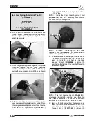
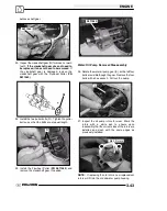
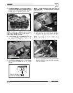
13. Install piston assemblies into cylinder aligning the
piston pin holes, to ensure proper alignment of the
pistons to the connecting rods upon assembly.
Partially install the piston pins into the pistons.
Cylinder Installation
NOTE:
To help align the pistons, slide a rod that is
close to the same diameter as the wrist pin holes to
properly align them in the cylinder.
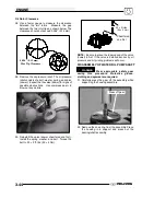
14. Position cylinder and piston assemblies onto the
connecting rods and push the piston pins through
the piston and connecting rods.
Push in Piston Pins
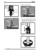
15. Install the piston pin keepers (F). The pin keeper
ends should be installed at the 12 O’clock
position.
Place Pin Keeper (F)
in 12 O’clock position
NOTE:
While installing in piston pins, cover all
engine passages. The clip could fall into the engine
during installation.
F
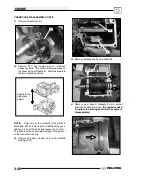
16. Install camshaft thrust plate (G) with new bolts.
Torque bolts to 115
±
12 in.lbs. (13
±
1.35 Nm).
NOTE:
New bolts have patch lock on the threads and
do not require Loctite
t
.
G
17. Assemble rotors as marked when disassembled.
Use a cleaner to remove the marks previously
made on the rotors.
Summary of Contents for Sportsman 800 Efi 2005
Page 116: ...ENGINE 3 62 NOTES ...
Page 136: ...FUEL SYSTEM FUEL INJECTION 4 20 NOTES ...
Page 186: ...CLUTCH 6 30 NOTES ...
Page 256: ...BRAKES 9 24 NOTES ...
Page 292: ...ELECTRICAL 10 36 BASIC WINCH WIRING 2005 ATV MODELS 2005 ATV WINCH WIRING DIAGRAM ...
Page 300: ...ELECTRICAL 10 44 NOTES ...
Page 301: ...ELECTRICAL 10 39 WIRING DIAGRAM 2005 SPORTSMAN 700 800 EFI Stator ...
Page 302: ...ELECTRICAL 10 40 WIRING DIAGRAM 2005 SPORTSMAN 700 800 EFI ...

