ENGINE
3.51
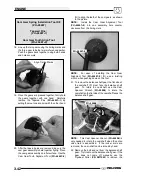
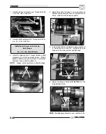
Line Up Marks
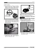
18. Apply moly lube, lubriplate, or oil to the rotors on
the oil pump shaft.
NOTE:
The application of oil or lubriplate aids in
priming the oil pump during initial engine start up.
Lubricate Rotors
19. Align the bolt holes and install oil pump assembly
into crankcase. Rotate the rotors in the housing
during installation, as this checks for binding if new
rotors are used.
NOTE:
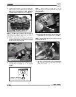
For assembly of the gears, the cam gear and
the crankshaft gear are stamped with “This Side Out.”
This indicates the side of the gear that faces outward
or away from the case.
This Side Out
NOTE:
Before assembly, clean the bolts and bolt
holes with Primer N (
PN 2870585
) to remove any
debris. This will ensure proper sealing when installing
bolts and new Loctite
t
.
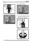
20. Install oil pump housing bolts (H). The new bolts
contain patch lock, so Loctite
t
is not needed on
the new bolts. Torque bolts to 84
±
8 in.lbs. (9.50
±
0.90 Nm) and follow the torque sequence on Pg.
3.3.
NOTE:
Occasionally spin the oil pump when
installing bolts to check for binding of the rotors.
H
Oil Pump Bolt Torque:
84
±
8 in.lbs. (9.50
±
0.90 Nm)
*Torque in Proper Sequence (Pg. 3.3)
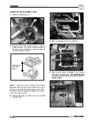
21. Apply Loctite
t
242 (
PN
2871949
) to the
crankshaft.
22. Before installing the crankshaft gear (I), heat the
crankshaft gear to 250
°
F (121
°
C) on a hot plate
Summary of Contents for Sportsman 800 Efi 2005
Page 116: ...ENGINE 3 62 NOTES ...
Page 136: ...FUEL SYSTEM FUEL INJECTION 4 20 NOTES ...
Page 186: ...CLUTCH 6 30 NOTES ...
Page 256: ...BRAKES 9 24 NOTES ...
Page 292: ...ELECTRICAL 10 36 BASIC WINCH WIRING 2005 ATV MODELS 2005 ATV WINCH WIRING DIAGRAM ...
Page 300: ...ELECTRICAL 10 44 NOTES ...
Page 301: ...ELECTRICAL 10 39 WIRING DIAGRAM 2005 SPORTSMAN 700 800 EFI Stator ...
Page 302: ...ELECTRICAL 10 40 WIRING DIAGRAM 2005 SPORTSMAN 700 800 EFI ...

