FUEL SYSTEM / FUEL INJECTION
4.15
THROTTLE POSITION
SENSOR (TPS)
The throttle position sensor (TPS) is used to indicate
throttle plate angle to the ECU.
Mounted on the throttle body and operated directly off
the end of the throttle shaft, the TPS works like a
rheostat, varying the voltage signal to the ECU in
direct correlation to the angle of the throttle plate. This
signal is processed by the ECU and compared to the
internal pre--programmed maps to determine the
required fuel and ignition settings for the amount of
engine load.
NOTE:
The correct position of the TPS is
established and set at the factory. Do not loosen
the TPS or alter the mounting position. If the TPS
is repositioned, replaced or loosened it must be
recalibrated.
THROTTLE POSITION SENSOR TEST
The throttle position sensor (TPS) is a non--serviceable
item. If it is faulty, it must be replaced. It can be tested
using the following method:
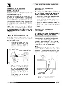
G
Set up the TPS voltage check tool,
PN PU--47082, according to the
instructions. Make sure that the 9 volt
battery has a minimum of 6 volts.
Figure 2
.
Figure 2
Red
Pink
Black
No ’Jumps’ in read--out
.70--.99v
Vdc
Black Probe
Red Probe
Tool PN PU--47082
R Y
BK
G
With the test leads connected and
the meter set, move the throttle open
and closed slowly while reading the
display. The voltage should increase
smoothly
with
no
’jumps’
or
decreases when the throttle is
applied.
G
If the sensor does not function
correctly, replace it.
THROTTLE POSITION SENSOR
REPLACEMENT
The correct position of the TPS is established and
set at the factory. If the TPS is repositioned,
replaced or loosened it must be recalibrated.
1. Remove the front fender assembly and fuel tank.
2. Disconnect sensor from the harness.
3. Loosen and rotate the throttle body to gain access
to the retaining screw.
4. Remove the retaining screw and replace the
sensor.
5. Refer to “TPS Initialization” for setting the TPS
voltage.
THROTTLE POSITION SENSOR
INITIALIZATION
The correct position of the TPS is established and
set at the factory. Use this procedure only if the
TPS was repositioned, replaced or loosened.
This set procedure can be accomplished with the
throttle body attached to the engine. This
procedure is meant to allow the TPS flow and idle
offset voltage to be correctly set without the use of
a flow bench. No steps can be eliminated.
Step 1
Establishing zero offset voltage:
This step is
crucial as it sets the TPS position using a fixed
physical stop. This will insure that the correct offset
voltage is reached once the correct throttle body flow
is set.
Figure 1
Throttle Plate
must be closed
G
Remove cover and disconnect
throttle cable from throttle cam.
Summary of Contents for Sportsman 800 Efi 2005
Page 116: ...ENGINE 3 62 NOTES ...
Page 136: ...FUEL SYSTEM FUEL INJECTION 4 20 NOTES ...
Page 186: ...CLUTCH 6 30 NOTES ...
Page 256: ...BRAKES 9 24 NOTES ...
Page 292: ...ELECTRICAL 10 36 BASIC WINCH WIRING 2005 ATV MODELS 2005 ATV WINCH WIRING DIAGRAM ...
Page 300: ...ELECTRICAL 10 44 NOTES ...
Page 301: ...ELECTRICAL 10 39 WIRING DIAGRAM 2005 SPORTSMAN 700 800 EFI Stator ...
Page 302: ...ELECTRICAL 10 40 WIRING DIAGRAM 2005 SPORTSMAN 700 800 EFI ...

