CLUTCH
6.20
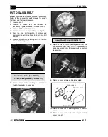
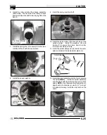
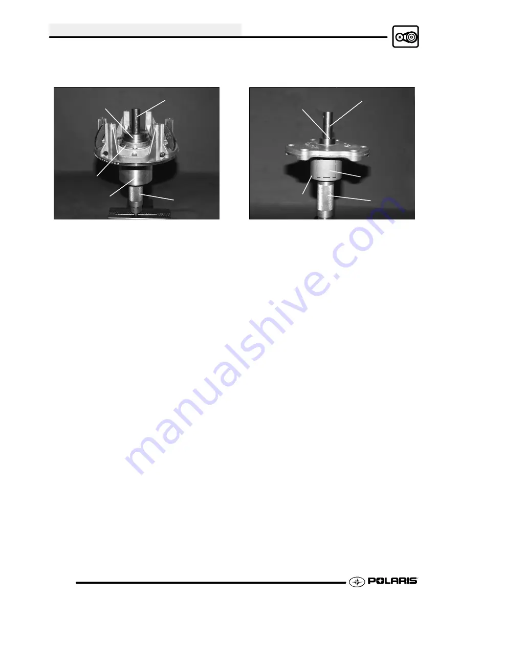
EBS Drive Moveable Bushing Installation
1. Place main adapter (Item 8) on puller.
Main Adapter
(8)
Piston Pin
Puller
Nut (C)
Bushing
EBS Drive Clutch Moveable Sheave
Bushing Installation
Puller Tool (A/B)
Side “A” toward
sheave
2. Apply Loctite
t
609 evenly to bushing bore inside
moveable sheave.
3. Set bushing in place on sheave.
4. Insert installation puller tool (Item A/B) with “A”
side down, into center of bushing.
800 EFI
Clutch -- Use Bushing Tool PA--47336.
5. With towers pointing upward, slide sheave,
bushing and tool onto puller rod.
6. Install nut on puller rod and hand tighten. Turn
barrel to apply additional tension if needed.
7. Turn sheave counterclockwise, making sure
bushing is drawn straight into bore. Continue until
bushing is seated.
8. Remove nut from puller rod and set aside.
9. Remove sheave from puller.
10. Remove installation tool.
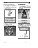
EBS Drive Clutch Cover Bushing Removal
1. Install main adapter (Item 8) on puller.
Main Adapter
(8)
Removal Tool (3)
Piston Pin
Puller
Nut (C)
Adapter
Reducer (9)
EBS Drive Clutch Cover Bushing Removal
2. Install adapter reducer (Item 9).
3. From outside of clutch cover, insert removal tool
(Item 3) into cover bushing.
4. With inside of cover toward vise, slide cover onto
puller.
5. Install nut onto puller rod and hand tighten. Turn
puller barrel to increase tension as needed.
6. Turn clutch cover counterclockwise on puller rod
until bushing is removed and cover comes free.
7. Remove nut from puller rod and set aside.
8. Remove bushing and bushing removal tool from
puller. Discard bushing.
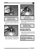
EBS Drive Clutch Cover Bushing Installation
1. Apply Loctite
t
609 evenly to bushing bore in
cover.
2. Working from inside of cover, insert new bushing
and bushing installation tool into center of clutch
cover.
3. With main adapter on puller, insert cover onto
puller rod, placing outside of cover toward vise.
4. Install nut on rod and hand tighten. Turn puller
barrel to apply more tension if needed.
5. Turn clutch cover counterclockwise on puller rod
until bushing is seated.
6. Remove nut from puller rod. Take installation tool
and clutch cover off rod.
Summary of Contents for Sportsman 800 Efi 2005
Page 116: ...ENGINE 3 62 NOTES ...
Page 136: ...FUEL SYSTEM FUEL INJECTION 4 20 NOTES ...
Page 186: ...CLUTCH 6 30 NOTES ...
Page 256: ...BRAKES 9 24 NOTES ...
Page 292: ...ELECTRICAL 10 36 BASIC WINCH WIRING 2005 ATV MODELS 2005 ATV WINCH WIRING DIAGRAM ...
Page 300: ...ELECTRICAL 10 44 NOTES ...
Page 301: ...ELECTRICAL 10 39 WIRING DIAGRAM 2005 SPORTSMAN 700 800 EFI Stator ...
Page 302: ...ELECTRICAL 10 40 WIRING DIAGRAM 2005 SPORTSMAN 700 800 EFI ...


