CLUTCH
6.26
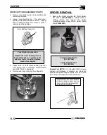
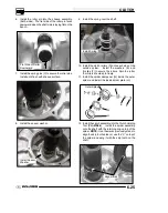
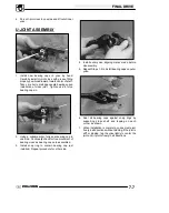
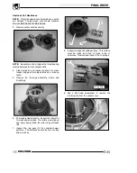
13. Install the compression cylinder of the holding tool
on top of the spider assembly and retaining ring.
Install the clutch holding tool handle and slowly
compress the spider onto the shaft. Align the
marks on the spider with the skip tooth on the
shaft.
PU--47086 Clutch
Compression Tool
14. Slowly compress the spider into place. If the
spider appears to bind while compressing, stop
and make sure the skip tooth on the shaft and the
spider are aligned. Once the spider passes the
retaining ring notch on the shaft, install the
retaining ring.
Retaining Ring
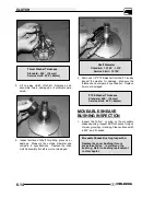
15. Install the cam assembly (helix) over the shaft.
Line up the “X” on the cam, “X” on spider, and “X”
on the stationary sheave or use the marks
previously made before disassembly.
NOTE:
If
the cam assembly (helix) is difficult to install, be
sure the sheaves are aligned. To align the
sheaves place the clutch assembly on a flat
surface with the cam assembly (helix) side down.
Press down on the moveable sheave belt face
with both hands and the helix will release.
Press Down to
Loosen Helix
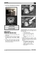
16. Use a T25 torx to install the four torx screws and
torque to 42--52 in. lbs. (4.75 -- 5.88 Nm) in a star
pattern.
Torque: 42--52 in. lbs.
(4.75--5.88 Nm)
Summary of Contents for Sportsman 800 Efi 2005
Page 116: ...ENGINE 3 62 NOTES ...
Page 136: ...FUEL SYSTEM FUEL INJECTION 4 20 NOTES ...
Page 186: ...CLUTCH 6 30 NOTES ...
Page 256: ...BRAKES 9 24 NOTES ...
Page 292: ...ELECTRICAL 10 36 BASIC WINCH WIRING 2005 ATV MODELS 2005 ATV WINCH WIRING DIAGRAM ...
Page 300: ...ELECTRICAL 10 44 NOTES ...
Page 301: ...ELECTRICAL 10 39 WIRING DIAGRAM 2005 SPORTSMAN 700 800 EFI Stator ...
Page 302: ...ELECTRICAL 10 40 WIRING DIAGRAM 2005 SPORTSMAN 700 800 EFI ...

