FINAL DRIVE
7.13
K
L
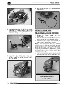
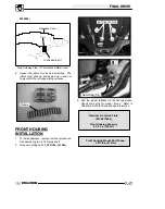
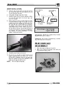
16. Remove the input cover (M), bearing (N), and the
pinion gear (O). Inspect the pinion gear (O) for
chipped, broken, or missing teeth. Replace the
input cover O--ring.
M
N
O
17. Inspect the output shaft bushing. Replace as
needed.
Clean the inside surfaces of both
gearcase halves.
18. Remove and replace the O--rings and seals from
the assembly.
FRONT GEARCASE
REASSEMBLY/INSPECTION
1. Replace
all
O--rings,
seals,
and
worn
components.
2. Press the pinion shaft seal into the pinion cover,
until the seal is flush with the sealing surface.
3. Inspect bearings on output and pinion shafts. To
replace, press new bearing on to shaft.
NOTE:
Due to extremely close tolerances and
minimal wear, the bearings must be inspected
visually, and by feel. While rotating bearings by hand,
inspect for rough spots, discoloration, or corrosion.
The bearings should turn smoothly and quietly, with
no detectable up and down movement and minimal
movement side to side.
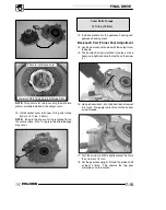
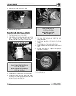
4. Install pinion shaft, bearing, and input cover with
new o-ring and torque bolts to 14 ft. lbs (19 Nm).
Input Cover Bolts Torque:
14 ft. lbs. (19 Nm)
Summary of Contents for Sportsman 800 Efi 2005
Page 116: ...ENGINE 3 62 NOTES ...
Page 136: ...FUEL SYSTEM FUEL INJECTION 4 20 NOTES ...
Page 186: ...CLUTCH 6 30 NOTES ...
Page 256: ...BRAKES 9 24 NOTES ...
Page 292: ...ELECTRICAL 10 36 BASIC WINCH WIRING 2005 ATV MODELS 2005 ATV WINCH WIRING DIAGRAM ...
Page 300: ...ELECTRICAL 10 44 NOTES ...
Page 301: ...ELECTRICAL 10 39 WIRING DIAGRAM 2005 SPORTSMAN 700 800 EFI Stator ...
Page 302: ...ELECTRICAL 10 40 WIRING DIAGRAM 2005 SPORTSMAN 700 800 EFI ...


