FINAL DRIVE
7.14
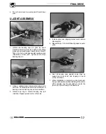
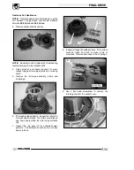
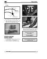
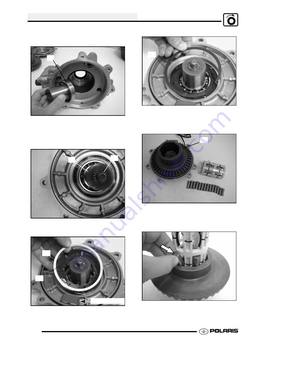
5. Install the output hub (A) into the gearcase
housing. The output hub should spin freely.
A
6. Install the other output hub (B) and thrust bearing
(C) into the output cover. Apply a small amount of
grease onto the thrust bearing.
C
B
7. Install the armature plate (D) and spacer washer
(E) into the output cover.
NOTE:
Be sure
backlash plate in in place.
E
D
Backlash Plate
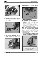
8. Install the retaining ring (F) into the output cover.
Be sure the retaining ring is properly seated into
the cover.
F
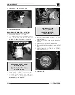
9. Install the ring gear onto the output hub on the
output cover.
G
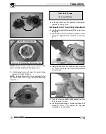
10. Install the rollers and roll cage into the ring gear.
Insert the rollers as the roll cage is installed.
11. Install the output cover assembly onto the main
gearcase.
NOTE:
Be sure armature plate tabs are placed into
the slots on roll cage. (See Reference Photo)
Summary of Contents for Sportsman 800 Efi 2005
Page 116: ...ENGINE 3 62 NOTES ...
Page 136: ...FUEL SYSTEM FUEL INJECTION 4 20 NOTES ...
Page 186: ...CLUTCH 6 30 NOTES ...
Page 256: ...BRAKES 9 24 NOTES ...
Page 292: ...ELECTRICAL 10 36 BASIC WINCH WIRING 2005 ATV MODELS 2005 ATV WINCH WIRING DIAGRAM ...
Page 300: ...ELECTRICAL 10 44 NOTES ...
Page 301: ...ELECTRICAL 10 39 WIRING DIAGRAM 2005 SPORTSMAN 700 800 EFI Stator ...
Page 302: ...ELECTRICAL 10 40 WIRING DIAGRAM 2005 SPORTSMAN 700 800 EFI ...


