TRANSMISSION
8.7
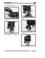
NOTE:
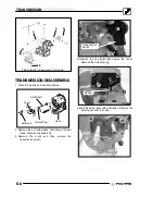
It may be helpful to place a mark just above
the keyed spline. Note the raised edge on the detent
gear for reassembly.
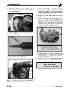
6. Mark the shift lockout disc, this will indicate which
side of the disc faces outward during assembly.
Remove the shift lockout disc.
NOTE:
It may be helpful to place a mark just above
the keyed spline. Note the raised edge on the detent
gear for reassembly.
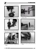
7. Remove the shift shaft and detent lever.
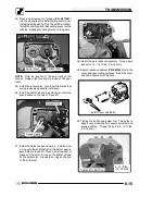
8. Note the timing marks on the shift gears. Remove
the shift gears from the case.
NOTE:
You may have to tap the shift drum from the
backside of the case to aid in removal.
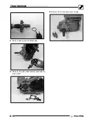
9. Remove the upper gear cluster and shift forks. You
may need to move the assembly back and forth to
aid in removal.
10. Set the upper gear cluster on a flat surface and
inspect the components.
Summary of Contents for Sportsman 800 Efi 2005
Page 116: ...ENGINE 3 62 NOTES ...
Page 136: ...FUEL SYSTEM FUEL INJECTION 4 20 NOTES ...
Page 186: ...CLUTCH 6 30 NOTES ...
Page 256: ...BRAKES 9 24 NOTES ...
Page 292: ...ELECTRICAL 10 36 BASIC WINCH WIRING 2005 ATV MODELS 2005 ATV WINCH WIRING DIAGRAM ...
Page 300: ...ELECTRICAL 10 44 NOTES ...
Page 301: ...ELECTRICAL 10 39 WIRING DIAGRAM 2005 SPORTSMAN 700 800 EFI Stator ...
Page 302: ...ELECTRICAL 10 40 WIRING DIAGRAM 2005 SPORTSMAN 700 800 EFI ...

