TRANSMISSION
8.14
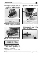
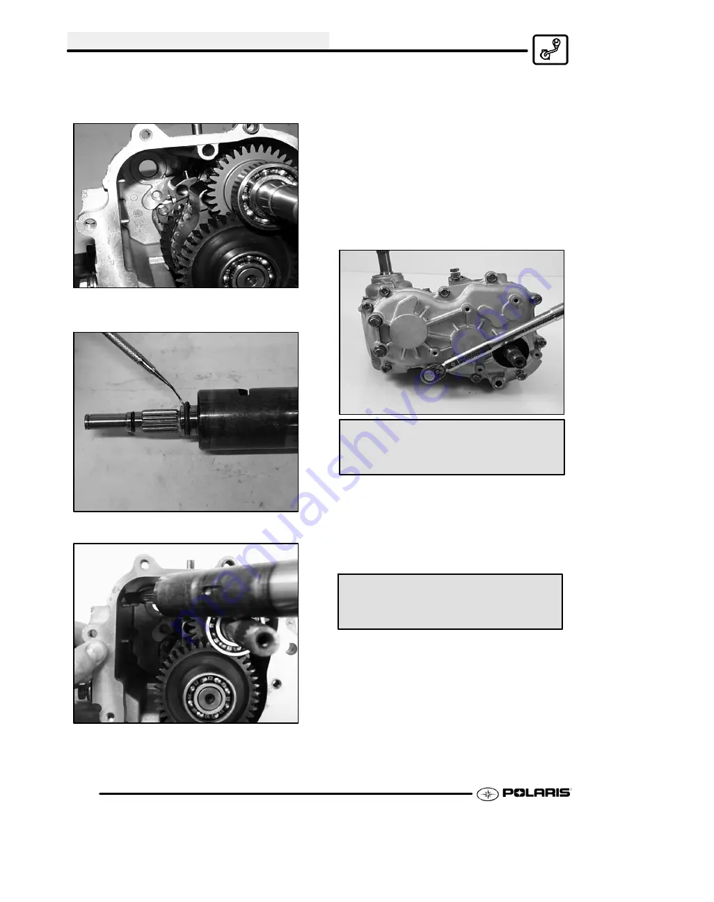
16. Position the shift forks up and so the the pins point
toward the 9 o’clock position, before installing the
shift drum assembly.
17. Replace and grease the O--rings on the shift drum
before installation.
18. Install the shift drum into the case.
NOTE:
Make sure shift shaft pins are properly
positioned in the slot on selector arms.
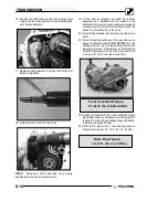
19. Lift the shift rail slightly and rotate the rail/fork
assembly so it meshes with the tracks on the
shiftdrum. Be sure the wave springs are properly
in place and that the shift rail is seated into the
pocket on the backside of the case.
20. Install the helical gear and bearing onto the pinion
shaft.
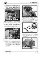
21. Clean the mating surfaces of the case and cover.
Apply Crankcase Sealant (
PN 2871557
) to the
mating surfaces. Be sure the locating pins (knock
pipes) are in place. Reinstall cover, LH mounting
bracket and torque bolts in a criss-cross pattern in
3 steps to 27--34 ft. lbs. (36.50--46 Nm).
Front Cover Bolt Torque:
27--34 ft. lbs. (36.50--46 Nm)
22. Grease the seal lips of the input shaft seal. Apply
electricians tape or somehow cover the splines of
the shaft to protect the seal lips during installation.
Install new input shaft seal.
23. Install drain plug with a new sealing washer.
Torque drain plug to 14--18 ft. lbs. (19--24 Nm).
Drain Plug Torque:
10--14 ft. lbs. (14--19 Nm)
Summary of Contents for Sportsman 800 Efi 2005
Page 116: ...ENGINE 3 62 NOTES ...
Page 136: ...FUEL SYSTEM FUEL INJECTION 4 20 NOTES ...
Page 186: ...CLUTCH 6 30 NOTES ...
Page 256: ...BRAKES 9 24 NOTES ...
Page 292: ...ELECTRICAL 10 36 BASIC WINCH WIRING 2005 ATV MODELS 2005 ATV WINCH WIRING DIAGRAM ...
Page 300: ...ELECTRICAL 10 44 NOTES ...
Page 301: ...ELECTRICAL 10 39 WIRING DIAGRAM 2005 SPORTSMAN 700 800 EFI Stator ...
Page 302: ...ELECTRICAL 10 40 WIRING DIAGRAM 2005 SPORTSMAN 700 800 EFI ...


