ENGINE
3.25
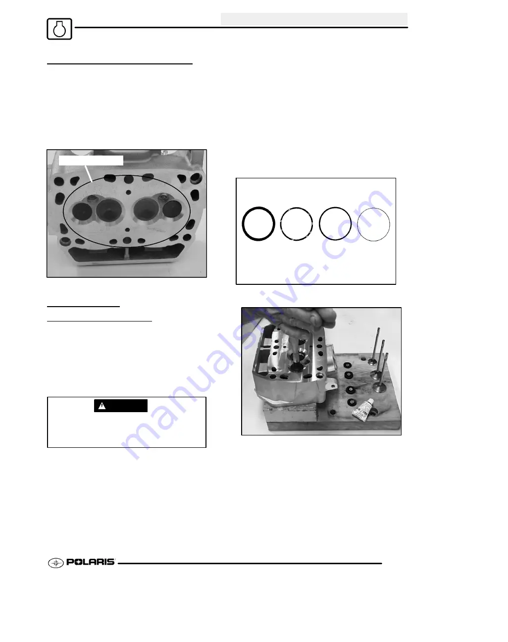
COMBUSTION CHAMBER
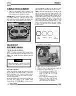
1. Clean all accumulated carbon deposits from
combustion chamber and valve seat area with
carbon cleaner and a soft plastic scraper.
IMPORTANT:
Do not use a wire brush, metal scraper,
or abrasive cleaners to clean the bottom of the
cylinder head. Extensive damage to the cylinder head
may result. Wear safety glasses during cleaning.
Combustion Area
VALVE SEAT
RECONDITIONING
Cylinder Head Reconditioning
NOTE:
Polaris recommends that the work be done
by a local machine shop that specializes in this area.
NOTE:
The cylinder head valve guides cannot be
replaced.
WARNING
Wear eye protection or a face shield during
cylinder head disassembly and reassembly.
Valve Seat Inspection
Inspect valve seat in cylinder head for pitting, burnt
spots, roughness, and uneven surface. If any of the
above conditions exist, the valve seat must be
reconditioned.
If the valve seat is cracked the cylinder
head must be replaced.
Follow the manufacturers instructions provided with
the valve seat cutters in the Cylinder Head
Reconditioning Kit (
PN 2200634
). Abrasive stone
seat reconditioning equipment can also be used.
Keep all valves in order with their respective seat.
NOTE:
Valve seat width and point of contact on the
valve face is very important for proper sealing. The
valve must contact the valve seat over the entire
circumference of the seat, and the seat must be the
proper width all the way around. If the seat is uneven,
compression leakage will result. If the seat is too
wide, seat pressure is reduced, causing carbon
accumulation and possible compression loss. If the
seat is too narrow, heat transfer from valve to seat is
reduced. The valve may overheat and warp, resulting
in burnt valves.
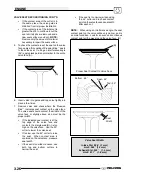
Too
Wide
Uneven
Good
Too
Narrow
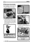
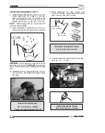
1. Install pilot into valve guide.
2. Apply cutting oil to valve seat and cutter.
3. Place 46
°
cutter on the pilot and make a light cut.
4. Inspect the cut area of the seat:
S
If the contact area is less than 75%
of the circumference of the seat,
rotate the pilot 180
°
and make
another light cut.
S
If the cutter now contacts the uncut
portion of the seat, check the pilot.
Look for burrs, nicks, or runout. If the
pilot is bent it must be replaced.
Summary of Contents for Sportsman 800 Efi 2005
Page 116: ...ENGINE 3 62 NOTES ...
Page 136: ...FUEL SYSTEM FUEL INJECTION 4 20 NOTES ...
Page 186: ...CLUTCH 6 30 NOTES ...
Page 256: ...BRAKES 9 24 NOTES ...
Page 292: ...ELECTRICAL 10 36 BASIC WINCH WIRING 2005 ATV MODELS 2005 ATV WINCH WIRING DIAGRAM ...
Page 300: ...ELECTRICAL 10 44 NOTES ...
Page 301: ...ELECTRICAL 10 39 WIRING DIAGRAM 2005 SPORTSMAN 700 800 EFI Stator ...
Page 302: ...ELECTRICAL 10 40 WIRING DIAGRAM 2005 SPORTSMAN 700 800 EFI ...

