ENGINE
3.30
ENGINE HEAD REASSEMBLY CONT’D
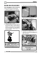
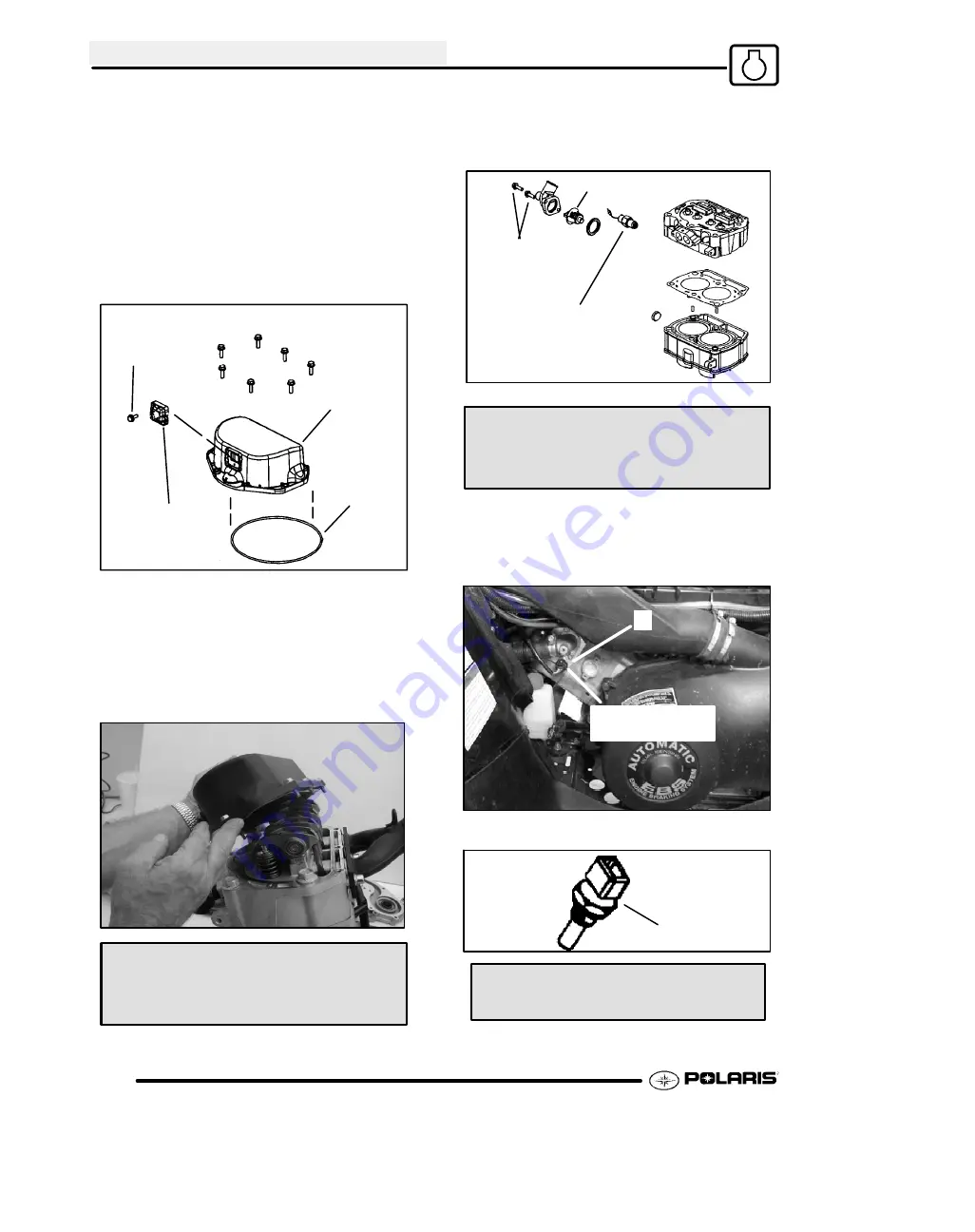
8. Install breather reed (G) into rocker cover (H).
Lightly apply black RTV sealant to the outer
edges of the breather reed. The reed has a tab
and will assemble one way only. Torque the
breather bolts to 20
±
5 in. lbs. (2.5
±
0.55 Nm).
NOTE:
When applying RTV, do not get any RTV
inside the reed assembly.
9. Place a
new
seal (I) into the bottom of the cover.
Be sure the seal is seated into the cover properly.
G
I
H
20
±
5 in.lbs.
(2.5
±
.55 Nm)
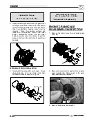
REMINDER:
Before assembly, clean the bolts and
bolt holes with Primer N (
PN 2870585
) to remove any
debris. This will ensure proper sealing when installing
bolts.
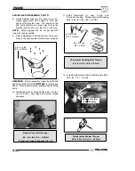
10. Install rocker cover. Torque bolts to 84
±
8 in.lbs.
(9.5
±
0.9 Nm). See Page 3.6 for proper torque
sequence.
Rocker Cover Bolt Torque:
84
±
8 in. lbs. (9.5
±
0.9 Nm)
*Torque In Proper Sequence (Pg. 3.6)
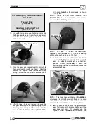
11. Install thermostat (J), new O--ring, and
thermostat housing. Torque thermostat housing
bolts to 84
±
8 in.lbs. (9.5
±
0.9 Nm).
J
84
±
8 in.lbs.
(9.5
±
0.9 Nm)
25
±
3 ft. lbs.
(34
±
4 Nm)
Thermostat Housing Bolt Torque:
84
±
8 in. lbs. (9.5
±
0.9 Nm)
12. Install temperature sender (K) and torque to 200
±
20 in. lbs. (1.4
±
.14 Nm).
200
±
20 in. lbs.
(1.4
±
.14 Nm)
K
K
Temperature Sender Torque:
200
±
20 in. lbs. (1.4
±
.14 Nm)
Summary of Contents for Sportsman 800 Efi 2005
Page 116: ...ENGINE 3 62 NOTES ...
Page 136: ...FUEL SYSTEM FUEL INJECTION 4 20 NOTES ...
Page 186: ...CLUTCH 6 30 NOTES ...
Page 256: ...BRAKES 9 24 NOTES ...
Page 292: ...ELECTRICAL 10 36 BASIC WINCH WIRING 2005 ATV MODELS 2005 ATV WINCH WIRING DIAGRAM ...
Page 300: ...ELECTRICAL 10 44 NOTES ...
Page 301: ...ELECTRICAL 10 39 WIRING DIAGRAM 2005 SPORTSMAN 700 800 EFI Stator ...
Page 302: ...ELECTRICAL 10 40 WIRING DIAGRAM 2005 SPORTSMAN 700 800 EFI ...


