ENGINE
3.37
FLYWHEEL/STATOR
REMOVAL/INSPECTION
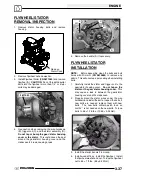
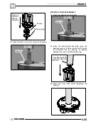
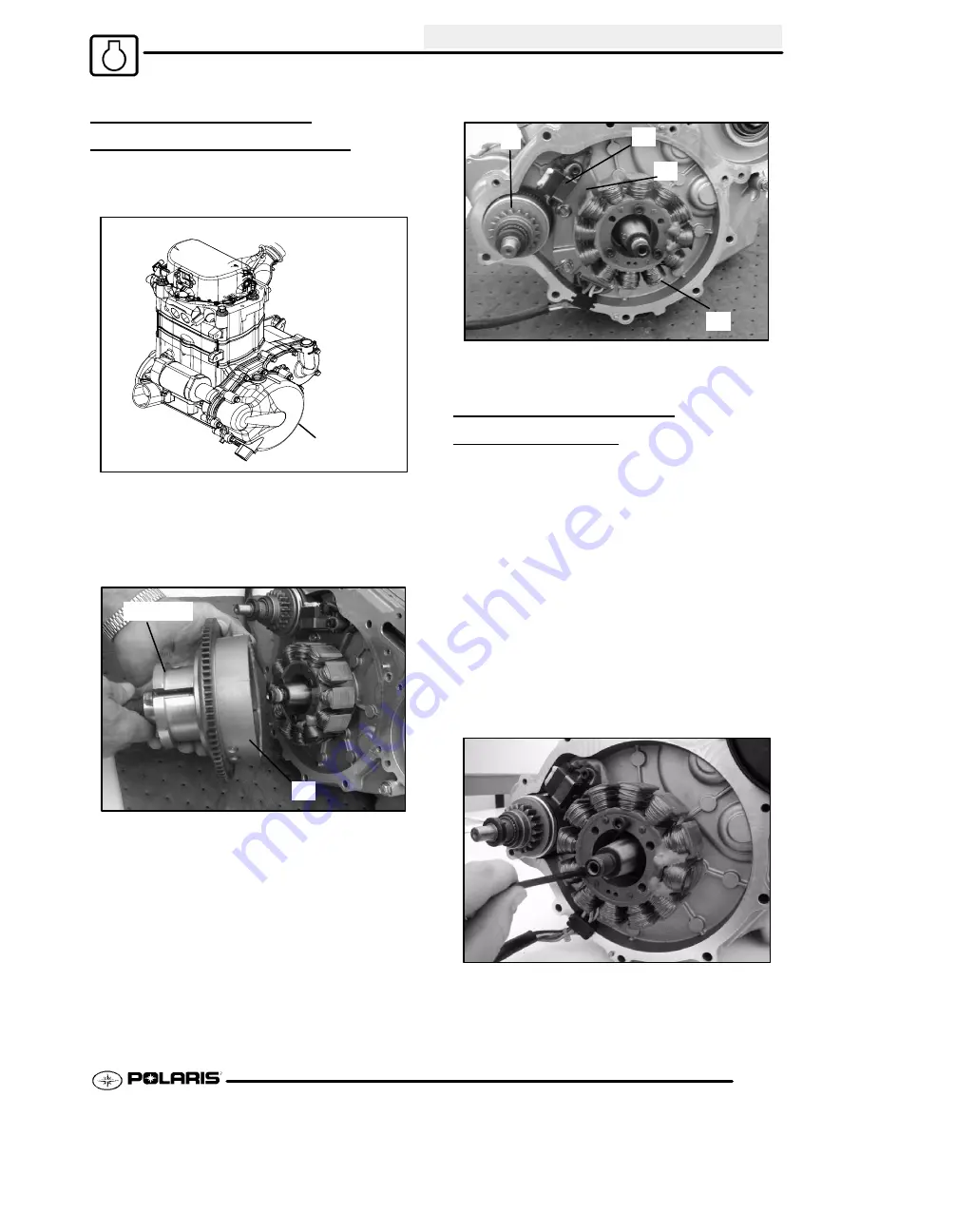
1. Remove stator housing bolts and remove
housing.
Remove
Stator Cover
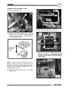
2. Remove flywheel nut and washer.
3. Install Flywheel Puller (
PN 2871043
) and remove
flywheel (A).
CAUTION:
Do not thread the puller
bolts into the flywheel more than 1/4
″
or stator
coils may be damaged.
2871043
A
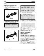
4. Use caution when removing the wire holddown
(B), trigger coil (C), and the stator assembly (D).
Do not tap or bump the gear /stator housing
cover or the stator
. This could cause the seal
around the gear/stator housing cover and the
crankcase to break, causing a leak.
D
C
E
B
5. Remove the bendix (E) if necessary.
FLYWHEEL/STATOR
INSTALLATION
NOTE:
Before assembly, clean the bolts and bolt
holes with Primer N (
PN 2870585
) to remove any
debris. This will ensure proper sealing when installing
bolts.
1. Carefully install the stator and trigger coil to the
gear/stator housing cover.
Do not tap on the
stator or the gear stator housing cover.
This
may cause a leak in between the gear/stator
housing cover and the crankcase.
2. Properly place the stator wires under the wire
holddown and install the bolts. Inspect the bolts, if
new bolts are needed, replace them with new
bolts. The new bolts contain patch lock, so
Loctite
t
is not needed on the new bolts. Torque
bolts to 96
±
12 in.lbs. (10.85
±
0.35 Nm).
3. Install the starter bendix if removed.
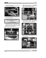
4. Install woodruff key. Install the flywheel. Install
the flywheel washer and nut. Torque the flywheel
nut to 65
±
7 ft.lbs. (88
±
9.50 Nm)
Summary of Contents for Sportsman 800 Efi 2005
Page 116: ...ENGINE 3 62 NOTES ...
Page 136: ...FUEL SYSTEM FUEL INJECTION 4 20 NOTES ...
Page 186: ...CLUTCH 6 30 NOTES ...
Page 256: ...BRAKES 9 24 NOTES ...
Page 292: ...ELECTRICAL 10 36 BASIC WINCH WIRING 2005 ATV MODELS 2005 ATV WINCH WIRING DIAGRAM ...
Page 300: ...ELECTRICAL 10 44 NOTES ...
Page 301: ...ELECTRICAL 10 39 WIRING DIAGRAM 2005 SPORTSMAN 700 800 EFI Stator ...
Page 302: ...ELECTRICAL 10 40 WIRING DIAGRAM 2005 SPORTSMAN 700 800 EFI ...


