ENGINE
3.39
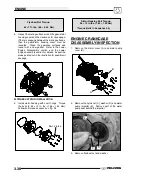
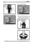
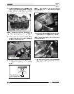
4. Install Flywheel Puller (
PN 2871043
) and remove
flywheel (F).
CAUTION:
Do not thread the puller
bolts into the flywheel more than 1/4
″
or stator
coils may be damaged.
2871043
F
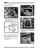
5. Remove the starter bendix (G), wire holddown
plate (H), and the woodruff key (I) from the
crankshaft. The stator does not have to be
removed at this point.
G
I
H
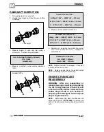
6. Remove the gear/stator housing bolts and
remove the gear/stator housing cover (J) and
gasket from the crankcase. Be sure to catch the
excess oil from the crankcase.
J
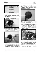
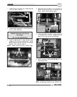
7. Note the positions of the gears in the photo.
Crank Gear
Counterbalance Gear
Camshaft Gear
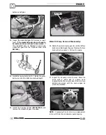
8. Use a white pen to accent the timing marks on the
following gears: camshaft gear (K), crankshaft
gear (M), or counterbalance gear (N) This will
ensure proper gear alignment and timing during
reassembly of the gears.
Timing Marks
K
M
N
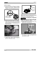
Water Pump Gear
Summary of Contents for Sportsman 800 Efi 2005
Page 116: ...ENGINE 3 62 NOTES ...
Page 136: ...FUEL SYSTEM FUEL INJECTION 4 20 NOTES ...
Page 186: ...CLUTCH 6 30 NOTES ...
Page 256: ...BRAKES 9 24 NOTES ...
Page 292: ...ELECTRICAL 10 36 BASIC WINCH WIRING 2005 ATV MODELS 2005 ATV WINCH WIRING DIAGRAM ...
Page 300: ...ELECTRICAL 10 44 NOTES ...
Page 301: ...ELECTRICAL 10 39 WIRING DIAGRAM 2005 SPORTSMAN 700 800 EFI Stator ...
Page 302: ...ELECTRICAL 10 40 WIRING DIAGRAM 2005 SPORTSMAN 700 800 EFI ...

