ENGINE
3.42
Cam Gear Spring Installation Tool Kit:
(PU--45497)
Tapered Pins:
(PU--45497--1)
Cam Gear Tooth Align Tool:
(PU--45497--2)
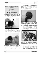
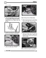
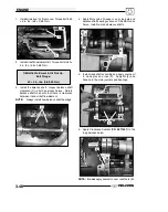
18. Line up the two gears using the timing marks and
the three gear tabs that were referenced earlier.
Push the gears back together, using both hands
and hold securely.
Align Timing Marks
19. Once the gears are pressed together, firmly hold
the gears together with one hand. Carefully
remove the Tapered Pins (
PU--45497--1
) by
pulling them out one at a time with the other hand.
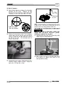
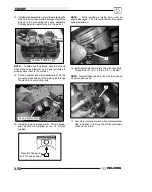
20. After the tapered pins are removed, be sure the
cam gear assembly is held together tightly. Place
the cam gear assembly on a flat surface. Use the
Cam Gear Tooth Alignment Tool (
PU--45497--2
)
(R) to align the teeth of the cam gears, as shown
in the picture.
NOTE:
Install the Cam Gear Alignment Tool
(
PU--45497--2
) into one assembly hole counter
clockwise from the timing mark.
PU--45497--2
NOTE:
For ease of installing the Cam Gear
Alignment Tool (
PU--45497--2
) (R), use a twisting
motion when pushing down on the tool.
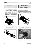
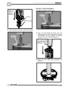
21. To remove the balance shaft gear, the flat side of
the camshaft (P) must face the balance shaft
gear. To rotate the camshaft, use the Cam
Spanner Wrench (
PU--45498
) to rotate the
camshaft so the flat side of the camshaft faces the
balance shaft gear.
PU--45498
P
NOTE:
This Cam Spanner Wrench (
PU--45498
) is
only needed to rotate the camshaft when the entire
valve train is assembled. If the rocker arms are
removed, the cam--shaft can be turned by hand.
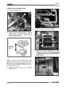
22. Remove the bolt and nut from the balance shaft
gear. Try to remove the balance shaft gear. If the
gear does not come off manually, use the
Flywheel Puller (
PN 2871043
) to remove the
Summary of Contents for Sportsman 800 Efi 2005
Page 116: ...ENGINE 3 62 NOTES ...
Page 136: ...FUEL SYSTEM FUEL INJECTION 4 20 NOTES ...
Page 186: ...CLUTCH 6 30 NOTES ...
Page 256: ...BRAKES 9 24 NOTES ...
Page 292: ...ELECTRICAL 10 36 BASIC WINCH WIRING 2005 ATV MODELS 2005 ATV WINCH WIRING DIAGRAM ...
Page 300: ...ELECTRICAL 10 44 NOTES ...
Page 301: ...ELECTRICAL 10 39 WIRING DIAGRAM 2005 SPORTSMAN 700 800 EFI Stator ...
Page 302: ...ELECTRICAL 10 40 WIRING DIAGRAM 2005 SPORTSMAN 700 800 EFI ...


