FUEL SYSTEM / FUEL INJECTION
4.13
FUEL INJECTOR SERVICE
Injector problems typically fall into three general
categories-- electrical, dirty/clogged, or leakage. An
electrical problem usually causes one or both of the
injectors to stop functioning. Several methods may be
used to check if the injectors are operating.
G
With the engine running at idle, feel
for operational vibration, indicating
that they are opening and closing.
G
When
temperatures
prohibit
touching, listen for a buzzing or
clicking sound with a screwdriver or
mechanic’s stethoscope.
G
Disconnect the electrical connector
from an injector and listen for a
change in idle performance (only
running on one cylinder) or a change
in injector noise or vibration.
NOTE:
Do not apply voltage directly to the fuel
injector(s). Excessive voltage will burn out the
injector(s). Do not ground the injector(s) with the
ignition “on.” lnjector(s) will open/turn on if relay is
energized.
If an injector is not operating, it can indicate either a
bad injector, or a wiring/electrical connection problem.
Check as follows:
Injector leakage is very unlikely, but in rare instances
it can be internal (past the tip of the valve needle), or
external (weeping around the injector body). The loss
of system pressure from the leakage can cause hot
restart problems and longer start--up times.
Injector problems due to dirt or clogging are unlikely
due to the design of the injectors, the high fuel
pressure, the use of filters and the detergent additives
in the gasoline. Symptoms that could be caused by
dirty/clogged
injectors
include
rough
idle,
hesitation/stumble during acceleration, or triggering
of fault codes related to fuel delivery. Injector clogging
is usually caused by a buildup of deposits on the
deflector plate, restricting the flow of fuel and resulting
in a poor spray pattern. Some contributing factors to
injector clogging include; dirty air filters, higher than
normal operating temperatures, short operating
intervals and dirty, incorrect, or poor quality fuel.
Cleaning of clogged injectors is not recommended;
they should be replaced. Additives and higher grades
of fuel can be used as a preventative measure if
clogging has been a problem.
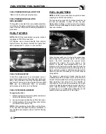
FUEL INJECTOR REPLACEMENT
1. Engine must be cool. Depressurize fuel system
through test valve in fuel rail.
2. Remove the front fender assembly and fuel tank.
3. Thoroughly clean the area around and including
the throttle body/manifold and the injectors.
4. Disconnect the fuel injector harness(s) at the
ECU.
5. Remove the fuel rail mounting screw and carefully
loosen / pull the rail away from the injectors.
6. Reverse the procedures to install the new
injector(s) and reassemble. Use new O--rings any
time an injector is removed (new replacement
injectors include new O--rings). Lubricate O--rings
lightly with oil to aid installation. Torque the fuel rail
mounting screw to 16--20 ft. lbs. (22.6--27 Nm).
CRANKSHAFT POSITION
SENSOR (CPS)
The engine speed sensor is essential to engine
operation, constantly monitoring the rotational speed
(RPM) of the crankshaft.
Crankshaft Position Sensor
A ferromagnetic 60--tooth ring gear with two
consecutive teeth missing is mounted on the flywheel.
The inductive speed sensor is mounted 1.0
±
0.26 mm
(0.059
±
0.010 in.) away from the ring gear. During
rotation, an AC pulse is created within the sensor for
each passing tooth. The ECU calculates engine
speed from the time interval between the consecutive
pulses. The two--tooth gap creates an “interrupt” input
signal, corresponding to specific crankshaft position
for PTO cylinder. This signal serves as a reference for
the control of ignition timing by the ECU.
Synchronization of the CPS and crankshaft position
takes place during the first two revolutions each time
the engine is started. This sensor must be properly
connected at all times. If the sensor fails or becomes
disconnected for any reason, the engine will quit
running.
Summary of Contents for Sportsman 800 Efi 2005
Page 116: ...ENGINE 3 62 NOTES ...
Page 136: ...FUEL SYSTEM FUEL INJECTION 4 20 NOTES ...
Page 186: ...CLUTCH 6 30 NOTES ...
Page 256: ...BRAKES 9 24 NOTES ...
Page 292: ...ELECTRICAL 10 36 BASIC WINCH WIRING 2005 ATV MODELS 2005 ATV WINCH WIRING DIAGRAM ...
Page 300: ...ELECTRICAL 10 44 NOTES ...
Page 301: ...ELECTRICAL 10 39 WIRING DIAGRAM 2005 SPORTSMAN 700 800 EFI Stator ...
Page 302: ...ELECTRICAL 10 40 WIRING DIAGRAM 2005 SPORTSMAN 700 800 EFI ...


