4.10
FUEL INJECTION
FUEL PUMP
Operation Overview
NOTE: All EFI units utilize quick connect lines. Fuel
Tank / Pump Assembly is a non-serviceable item and
must be replaced if determined to be at fault.
An electric fuel pump assembly is used to transfer fuel to the EFI
system from inside the fuel tank. This assembly includes the fuel
pump, regulator and fuel gauge sender. The pump is rated for a
minimum output of 25 liters per hour at 39 psi and has a non-
serviceable internal 30-micron filter.
When the key switch is turned to "ON", the ECU activates the
fuel pump, which pressurizes the system for start-up.
The ECU switches off the pump preventing the continued
delivery of fuel in these instances:
• If the key switch is not promptly turned to the "start"
position.
• If the engine fails to start, or
• If the engine is stopped with the key switch "on" (as in
the case of an accident)
In these situations, the “check engine” light will go on, but will
turn off after 4 cranking revolutions if system function is OK.
Once the engine is running, the fuel pump remains on.
Fuel Pump Test
NOTE: FUEL GAUGE SENDER TEST - To test fuel
gauge sender function, refer to Chapter 10.
The fuel pump/tank assembly is non-serviceable and must be
replaced if determined to be faulty. If a fuel delivery problem is
suspected, make certain the filter is not plugged, that the pump
is being activated through the ECU, all electrical connections
are properly secured, the fuses are good, and a minimum of 7.0
volts is being supplied. If during starting the battery voltage
drops below 7.0 volts, the ECU will fail to operate the system.
1.
Remove the fuel rail end cap (damper).
2.
Connect the fuel rail end cap (damper) onto adapter PU-
47476 and install on the fuel rail.
3.
Attach Polaris pressure tester PU-43506. Route the tester
clear hose into a portable gasoline container or the
equipment fuel tank.
4.
Turn on the key switch to activate the pump and check the
system pressure on the gauge. If system pressure of 39 psi
±
3 is observed, the ignition switch, ECU, fuel pump, and
pressure regulator are working properly. Turn the key
switch off and depress the valve button on the tester to
relieve the system pressure.
NOTE: If the pressure is too high or too low, replace
the fuel tank assembly.
Example Shown.
Fuel pump not replaceable.
For reference only.
Regulator
Fuel Pump
Internal 30 Micron
Strainer (Bottom)
Fuel Gauge Sender
WARNING
Check the fuel test valve for any possible fuel
seepage after performing any tests or procedures.
Fuel is extremely flammable and may cause severe
burns, injury, or death. Do not use any device that
produces a flame or electrical devices that may
spark around fuel or fuel vapors.
Normal Fuel Pressure: 39 psi. ± 3
Summary of Contents for Sportsman 800 EFI
Page 4: ...NOTES ...
Page 18: ...NOTES GENERAL INFORMATION 1 14 ...
Page 25: ...2 7 MAINTENANCE 2 LUBRICATION FLUIDS SPORTSMAN Component Locations Sportsman Only Deluxe ...
Page 56: ...2 38 MAINTENANCE Maintenance Schedule Service Date Hours Miles Service Performed Serviced By ...
Page 116: ...NOTES ENGINE 3 60 ...
Page 137: ...4 21 FUEL INJECTION 4 EFI CIRCUIT Power On EFI CIRCUIT Crank Position Sensor ...
Page 138: ...4 22 FUEL INJECTION EFI CIRCUIT Fuel Pump EFI CIRCUIT Throttle Position Sensor ...
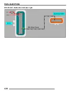
Page 140: ...4 24 FUEL INJECTION EFI CIRCUIT Malfunction Indicator Light ...
Page 167: ...5 27 BODY STEERING SUSPENSION 5 X2 CARGO BOX Exploded View ...
Page 170: ...5 30 BODY STEERING SUSPENSION X2 SEAT ASSEMBLY Exploded Views ...
Page 174: ...NOTES BODY STEERING SUSPENSION 5 34 ...
Page 206: ...NOTES CLUTCH SYSTEM 6 32 ...
Page 244: ...7 38 FINAL DRIVE Rear Gearcase Exploded View ...
Page 245: ...TRANSMISSION 8 1 CHAPTER 8 TRANSMISSION 8 SPORTSMAN 8 3 8 18 SPORTSMAN X2 8 19 8 38 ...
Page 246: ...NOTES TRANSMISSION 8 2 ...
Page 248: ...8 4 SPORTSMAN TRANSMISSION TRANSMISSION EXPLODED VIEW Sportsman Transmission ...
Page 265: ...8 21 X2 Touring Transmission 8 242 262 262 262 262 262 ...
Page 266: ...8 22 X2 Touring Transmission Mounting Exploded View x2 x3 x4 x4 x2 x1 x1 x1 ...
Page 312: ...NOTES BRAKES 9 30 ...
Page 322: ...10 10 ELECTRICAL SPEEDOMETER TROUBLESHOOTING Test 1 No All Wheel Drive ...
Page 323: ...10 11 ELECTRICAL 10 TEST 2 No Display TEST 3 No Reverse Speed Limit ...
Page 324: ...10 12 ELECTRICAL TEST 4 No AWD Hub Safety Limiter ...
Page 325: ...10 13 ELECTRICAL 10 TEST 5 Reverse Speed Limiter TEST 6 Speed Sensor ...
Page 326: ...10 14 ELECTRICAL TEST 7 No Fuel Gauge TEST 8 Transmission Switch ...
Page 357: ...10 45 ELECTRICAL 10 BASIC WINCH WIRING PRE WIRED MODELS ...
Page 367: ...10 55 ELECTRICAL 10 Cooling Fan EFI Fuel Pump EFI ...
Page 368: ...10 56 ELECTRICAL Gear Switch EFI Power Circuit EFI ...
Page 369: ...10 57 ELECTRICAL 10 Reverse Override EFI Fan Control EFI ...
Page 370: ...10 58 ELECTRICAL Start Circuit EFI Start Enable EFI ...
Page 373: ...11 3 800 TOURING EFI INTERNATIONAL 11 Exploded View Foot Brake Supply Hand Brake Supply ...
Page 376: ...NOTES 800 TOURING EFI INTERNATIONAL 11 6 ...
Page 382: ...IX 6 Intentional Blank Page ...
Page 383: ...WD 1 WIRE DIAGRAM 2008 SPORTSMAN 800 EFI WIRE DIAGRAM ...
Page 384: ...WD 2 WIRE DIAGRAM ...
Page 385: ...WD 3 WIRE DIAGRAM 2008 SPORTSMAN 700 X2 800 TOURING EFI WIRE DIAGRAM ...
Page 386: ...WD 4 WIRE DIAGRAM ...
Page 387: ...WD 5 WIRE DIAGRAM 2008 SPORTSMAN 800 TOURING EFI INTERNATIONAL WIRE DIAGRAM ...
Page 388: ...WD 6 WIRE DIAGRAM ...


