10.24
ELECTRICAL
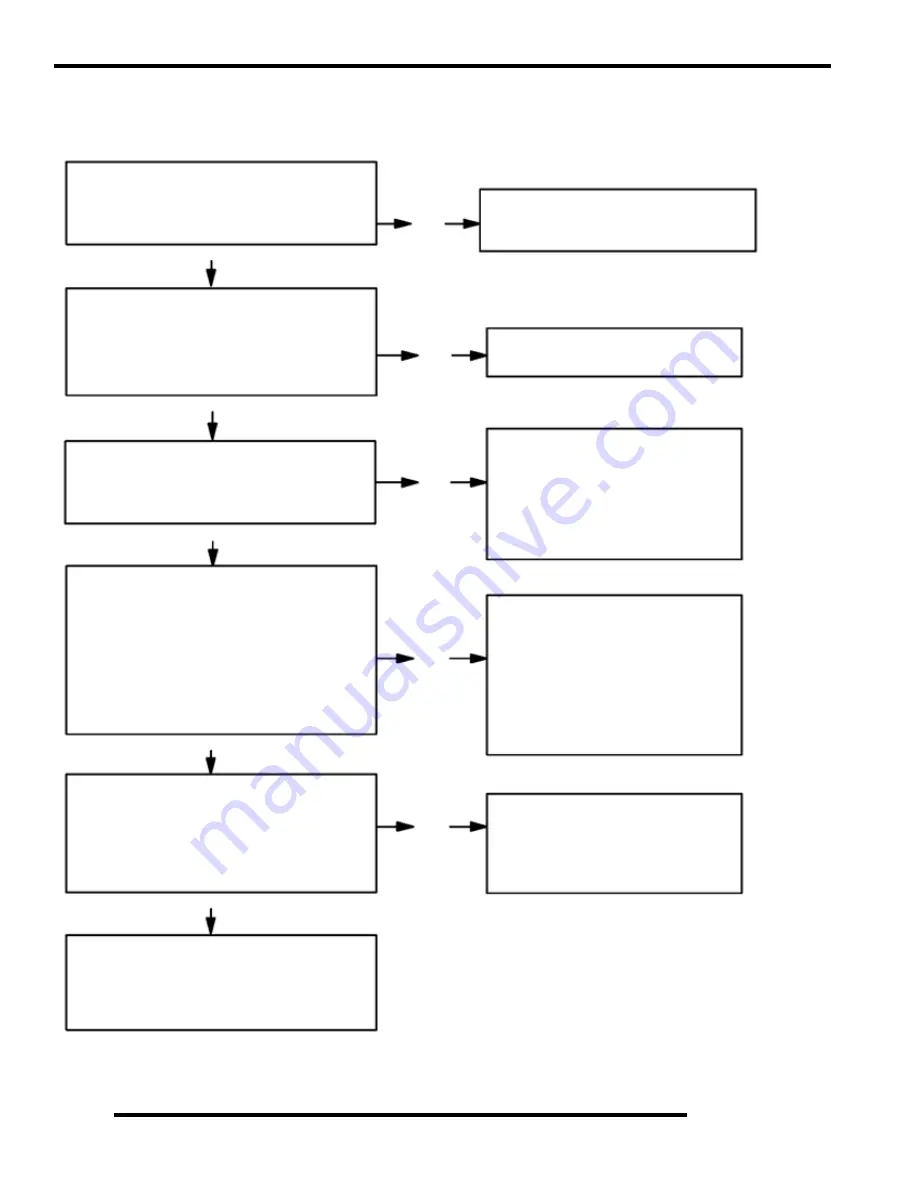
Charging System Testing Flow Chart
Whenever charging system problems are suspected, proceed with the following system check after verifying that all wires are in good
condition, connected and not kinked or pinched.
Using a multitester set on D.C. volts, measure the
battery open circuit voltage (See earlier test). It
should be 12.4 volts or more. Is it?
With the transmission in Park, start the engine and
increase RPM to between 3000 and 4000. Read
battery voltage with the multitester. Readings
should increase to between 13 and 14.6 VDC.
Are they?
Perform system Break Even Amperage Test"
Does charging occur as specified?
Meter Setting DC Amps
Meter Setting DC Volts
Ohm stator wires If bad, replace stator. If good,
continue with alternator output test.
Disconnect the wires from the regulator/rectifier.
Using a multitester, perform an Alternator Output
(AC amp) test. See test procedure on Page 10.20
for procedure. Is output above 7 amps?
Meter Setting AC Amps
Reconnect the alternator wires. Note: Red wire
must be connected to harness. Battery voltage must
be present on red wire terminal on harness side of
voltage regulator connector. Is it?
Meter Setting: DC Volts
If all of the previous tests indicate a good
condition, but the charging voltage does not rise
above battery voltage at the connector or wire
harness, replace the voltage regulator.
Yes
Yes
Yes
No
No
Remove the battery and properly service.
Reinstall the fully charged battery or a fully
charged shop battery.
No
Yes
Yes
No
No
Check Key Off Current Draw
Check for owner modification, and
discuss operating habits. The battery
will continually discharge if operated
below the “Break Even” RPM.
Continued problems would call for
battery inspection.
Inspect the wiring harness between the
panel and the stator for damage. If no
damage is found, remove the recoil and
flywheel. Inspect the flywheel magnets,
stator coils and stator wire harness for
damage. Repair or replace any damaged
components.
Check regulator/rectifier connections and
ground, battery connections, circuit
breaker and connecting wires. Repair or
replace faulty wiring or components.
Summary of Contents for Sportsman 800 EFI
Page 4: ...NOTES ...
Page 18: ...NOTES GENERAL INFORMATION 1 14 ...
Page 25: ...2 7 MAINTENANCE 2 LUBRICATION FLUIDS SPORTSMAN Component Locations Sportsman Only Deluxe ...
Page 56: ...2 38 MAINTENANCE Maintenance Schedule Service Date Hours Miles Service Performed Serviced By ...
Page 116: ...NOTES ENGINE 3 60 ...
Page 137: ...4 21 FUEL INJECTION 4 EFI CIRCUIT Power On EFI CIRCUIT Crank Position Sensor ...
Page 138: ...4 22 FUEL INJECTION EFI CIRCUIT Fuel Pump EFI CIRCUIT Throttle Position Sensor ...
Page 140: ...4 24 FUEL INJECTION EFI CIRCUIT Malfunction Indicator Light ...
Page 167: ...5 27 BODY STEERING SUSPENSION 5 X2 CARGO BOX Exploded View ...
Page 170: ...5 30 BODY STEERING SUSPENSION X2 SEAT ASSEMBLY Exploded Views ...
Page 174: ...NOTES BODY STEERING SUSPENSION 5 34 ...
Page 206: ...NOTES CLUTCH SYSTEM 6 32 ...
Page 244: ...7 38 FINAL DRIVE Rear Gearcase Exploded View ...
Page 245: ...TRANSMISSION 8 1 CHAPTER 8 TRANSMISSION 8 SPORTSMAN 8 3 8 18 SPORTSMAN X2 8 19 8 38 ...
Page 246: ...NOTES TRANSMISSION 8 2 ...
Page 248: ...8 4 SPORTSMAN TRANSMISSION TRANSMISSION EXPLODED VIEW Sportsman Transmission ...
Page 265: ...8 21 X2 Touring Transmission 8 242 262 262 262 262 262 ...
Page 266: ...8 22 X2 Touring Transmission Mounting Exploded View x2 x3 x4 x4 x2 x1 x1 x1 ...
Page 312: ...NOTES BRAKES 9 30 ...
Page 322: ...10 10 ELECTRICAL SPEEDOMETER TROUBLESHOOTING Test 1 No All Wheel Drive ...
Page 323: ...10 11 ELECTRICAL 10 TEST 2 No Display TEST 3 No Reverse Speed Limit ...
Page 324: ...10 12 ELECTRICAL TEST 4 No AWD Hub Safety Limiter ...
Page 325: ...10 13 ELECTRICAL 10 TEST 5 Reverse Speed Limiter TEST 6 Speed Sensor ...
Page 326: ...10 14 ELECTRICAL TEST 7 No Fuel Gauge TEST 8 Transmission Switch ...
Page 357: ...10 45 ELECTRICAL 10 BASIC WINCH WIRING PRE WIRED MODELS ...
Page 367: ...10 55 ELECTRICAL 10 Cooling Fan EFI Fuel Pump EFI ...
Page 368: ...10 56 ELECTRICAL Gear Switch EFI Power Circuit EFI ...
Page 369: ...10 57 ELECTRICAL 10 Reverse Override EFI Fan Control EFI ...
Page 370: ...10 58 ELECTRICAL Start Circuit EFI Start Enable EFI ...
Page 373: ...11 3 800 TOURING EFI INTERNATIONAL 11 Exploded View Foot Brake Supply Hand Brake Supply ...
Page 376: ...NOTES 800 TOURING EFI INTERNATIONAL 11 6 ...
Page 382: ...IX 6 Intentional Blank Page ...
Page 383: ...WD 1 WIRE DIAGRAM 2008 SPORTSMAN 800 EFI WIRE DIAGRAM ...
Page 384: ...WD 2 WIRE DIAGRAM ...
Page 385: ...WD 3 WIRE DIAGRAM 2008 SPORTSMAN 700 X2 800 TOURING EFI WIRE DIAGRAM ...
Page 386: ...WD 4 WIRE DIAGRAM ...
Page 387: ...WD 5 WIRE DIAGRAM 2008 SPORTSMAN 800 TOURING EFI INTERNATIONAL WIRE DIAGRAM ...
Page 388: ...WD 6 WIRE DIAGRAM ...


