2.25
MAINTENANCE
2
14. Start the engine and let it idle for one to two minutes. Stop
the engine and inspect for leaks.
15. Re-check the oil level on the dipstick and add oil as
necessary to bring the level to the upper mark on the
dipstick.
16. Dispose of used filter and oil properly.
Steering Inspection
The steering components should be checked periodically for
loose fasteners, worn tie rod ends, and damage. Also check to
make sure all cotter pins are in place. If cotter pins are removed,
they must not be re-used. Always use new cotter pins.
Replace any worn or damaged steering components. Steering
should move freely through entire range of travel without
binding. Check routing of all cables, hoses, and wiring to be
sure the steering mechanism is not restricted or limited.
NOTE:
Whenever steering components are
replaced, check front end alignment. Use only
genuine Polaris parts.
One of two methods can be used to measure toe alignment. The
string method and the chalk method. If adjustment is required,
refer to following pages for procedure.
Tie Rod / Steering
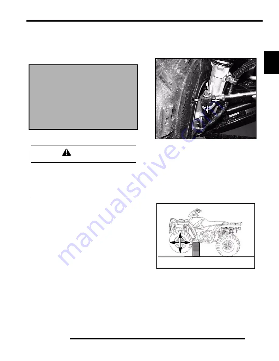
• To check for play in the tie rod end, grasp the steering
tie rod, pull in all directions feeling for movement.
• Repeat inspection for inner tie rod end on steering post.
• Replace any worn steering components. Steering
should move freely through entire range of travel
without binding.
• Elevate front end of machine so front wheels are off the
ground. Check for any looseness in front hub / wheel
assembly by grasping the tire firmly at top and bottom
first, and then at front and rear. Try to move the wheel
and hub by pushing inward and pulling outward.
• If abnormal movement is detected, inspect the hub and
wheel assembly to determine the cause ( possible loose
wheel nuts or loose front hub components).
• Refer to the Body/Steering Chapter 5 or Final Drive
Chapter 7 for service procedures.
Camber/Caster
Camber and caster are non-adjustable.
Recommended Engine Oil:
2W/50 Synthetic
Oil Filter Wrench: (PV-43527)
Oil Filter Torque: Turn by hand until filter
gasket contacts sealing surface, then turn an
additional 1/2 turn
WARNING
Due to the critical nature of the procedures outlined
in this chapter, Polaris recommends steering
component repair and adjustment be performed by
an authorized Polaris MSD-certified technician
when replacing worn or damaged steering parts.
Use only genuine Polaris replacement parts.
Check for loose wheel or hub.
Summary of Contents for Sportsman 800 EFI
Page 4: ...NOTES ...
Page 18: ...NOTES GENERAL INFORMATION 1 14 ...
Page 25: ...2 7 MAINTENANCE 2 LUBRICATION FLUIDS SPORTSMAN Component Locations Sportsman Only Deluxe ...
Page 56: ...2 38 MAINTENANCE Maintenance Schedule Service Date Hours Miles Service Performed Serviced By ...
Page 116: ...NOTES ENGINE 3 60 ...
Page 137: ...4 21 FUEL INJECTION 4 EFI CIRCUIT Power On EFI CIRCUIT Crank Position Sensor ...
Page 138: ...4 22 FUEL INJECTION EFI CIRCUIT Fuel Pump EFI CIRCUIT Throttle Position Sensor ...
Page 140: ...4 24 FUEL INJECTION EFI CIRCUIT Malfunction Indicator Light ...
Page 167: ...5 27 BODY STEERING SUSPENSION 5 X2 CARGO BOX Exploded View ...
Page 170: ...5 30 BODY STEERING SUSPENSION X2 SEAT ASSEMBLY Exploded Views ...
Page 174: ...NOTES BODY STEERING SUSPENSION 5 34 ...
Page 206: ...NOTES CLUTCH SYSTEM 6 32 ...
Page 244: ...7 38 FINAL DRIVE Rear Gearcase Exploded View ...
Page 245: ...TRANSMISSION 8 1 CHAPTER 8 TRANSMISSION 8 SPORTSMAN 8 3 8 18 SPORTSMAN X2 8 19 8 38 ...
Page 246: ...NOTES TRANSMISSION 8 2 ...
Page 248: ...8 4 SPORTSMAN TRANSMISSION TRANSMISSION EXPLODED VIEW Sportsman Transmission ...
Page 265: ...8 21 X2 Touring Transmission 8 242 262 262 262 262 262 ...
Page 266: ...8 22 X2 Touring Transmission Mounting Exploded View x2 x3 x4 x4 x2 x1 x1 x1 ...
Page 312: ...NOTES BRAKES 9 30 ...
Page 322: ...10 10 ELECTRICAL SPEEDOMETER TROUBLESHOOTING Test 1 No All Wheel Drive ...
Page 323: ...10 11 ELECTRICAL 10 TEST 2 No Display TEST 3 No Reverse Speed Limit ...
Page 324: ...10 12 ELECTRICAL TEST 4 No AWD Hub Safety Limiter ...
Page 325: ...10 13 ELECTRICAL 10 TEST 5 Reverse Speed Limiter TEST 6 Speed Sensor ...
Page 326: ...10 14 ELECTRICAL TEST 7 No Fuel Gauge TEST 8 Transmission Switch ...
Page 357: ...10 45 ELECTRICAL 10 BASIC WINCH WIRING PRE WIRED MODELS ...
Page 367: ...10 55 ELECTRICAL 10 Cooling Fan EFI Fuel Pump EFI ...
Page 368: ...10 56 ELECTRICAL Gear Switch EFI Power Circuit EFI ...
Page 369: ...10 57 ELECTRICAL 10 Reverse Override EFI Fan Control EFI ...
Page 370: ...10 58 ELECTRICAL Start Circuit EFI Start Enable EFI ...
Page 373: ...11 3 800 TOURING EFI INTERNATIONAL 11 Exploded View Foot Brake Supply Hand Brake Supply ...
Page 376: ...NOTES 800 TOURING EFI INTERNATIONAL 11 6 ...
Page 382: ...IX 6 Intentional Blank Page ...
Page 383: ...WD 1 WIRE DIAGRAM 2008 SPORTSMAN 800 EFI WIRE DIAGRAM ...
Page 384: ...WD 2 WIRE DIAGRAM ...
Page 385: ...WD 3 WIRE DIAGRAM 2008 SPORTSMAN 700 X2 800 TOURING EFI WIRE DIAGRAM ...
Page 386: ...WD 4 WIRE DIAGRAM ...
Page 387: ...WD 5 WIRE DIAGRAM 2008 SPORTSMAN 800 TOURING EFI INTERNATIONAL WIRE DIAGRAM ...
Page 388: ...WD 6 WIRE DIAGRAM ...


