3.25
ENGINE
3
Valve Inspection
1.
Remove all carbon from valves with a soft wire wheel or
brush.
2.
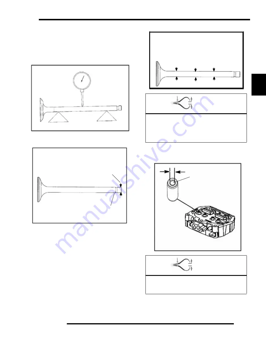
Check valve face for runout, pitting, and burnt spots. To
check for bent valve stems, mount valve in a drill or use “V”
blocks and a dial indicator.
3.
Check end of valve stem for flaring, pitting, wear or damage
(A).
4.
Inspect split keeper groove for wear or flaring of the keeper
seat area (B).
NOTE:
The valves can be re-faced or end
ground, if necessary. They must be replaced if extensively
worn, burnt, bent, or damaged.
5.
Measure diameter of valve stem with a micrometer in three
places, then rotate 90 degrees and measure again (six
measurements total). Compare to specifications.
6.
Measure valve guide (C) inside diameter at the top middle
and end of the guide using a small hole gauge and a
micrometer. Measure in two directions.
7.
Subtract valve stem measurement from the valve guide
measurement to obtain stem to guide clearance. NOTE:
The valve guides cannot be replaced. Be sure to measure
each guide and valve combination individually.
A
B
=
In. / mm.
Valve Stem Diameter:
Intake: 0.2356" + 0.00039"
(5.985 + 0.01 mm)
Exhaust: 0.2351" + 0.00039"
(5.972 + 0.01 mm)
=
In. / mm.
Valve Guide I.D.:
0.23672" + 0.000295"
(6.0617 + 0.0075 mm)
Measure valve stem in several places.
Rotate the valve 90 degrees and measure
for wear.
C
Summary of Contents for Sportsman 800 EFI
Page 4: ...NOTES ...
Page 18: ...NOTES GENERAL INFORMATION 1 14 ...
Page 25: ...2 7 MAINTENANCE 2 LUBRICATION FLUIDS SPORTSMAN Component Locations Sportsman Only Deluxe ...
Page 56: ...2 38 MAINTENANCE Maintenance Schedule Service Date Hours Miles Service Performed Serviced By ...
Page 116: ...NOTES ENGINE 3 60 ...
Page 137: ...4 21 FUEL INJECTION 4 EFI CIRCUIT Power On EFI CIRCUIT Crank Position Sensor ...
Page 138: ...4 22 FUEL INJECTION EFI CIRCUIT Fuel Pump EFI CIRCUIT Throttle Position Sensor ...
Page 140: ...4 24 FUEL INJECTION EFI CIRCUIT Malfunction Indicator Light ...
Page 167: ...5 27 BODY STEERING SUSPENSION 5 X2 CARGO BOX Exploded View ...
Page 170: ...5 30 BODY STEERING SUSPENSION X2 SEAT ASSEMBLY Exploded Views ...
Page 174: ...NOTES BODY STEERING SUSPENSION 5 34 ...
Page 206: ...NOTES CLUTCH SYSTEM 6 32 ...
Page 244: ...7 38 FINAL DRIVE Rear Gearcase Exploded View ...
Page 245: ...TRANSMISSION 8 1 CHAPTER 8 TRANSMISSION 8 SPORTSMAN 8 3 8 18 SPORTSMAN X2 8 19 8 38 ...
Page 246: ...NOTES TRANSMISSION 8 2 ...
Page 248: ...8 4 SPORTSMAN TRANSMISSION TRANSMISSION EXPLODED VIEW Sportsman Transmission ...
Page 265: ...8 21 X2 Touring Transmission 8 242 262 262 262 262 262 ...
Page 266: ...8 22 X2 Touring Transmission Mounting Exploded View x2 x3 x4 x4 x2 x1 x1 x1 ...
Page 312: ...NOTES BRAKES 9 30 ...
Page 322: ...10 10 ELECTRICAL SPEEDOMETER TROUBLESHOOTING Test 1 No All Wheel Drive ...
Page 323: ...10 11 ELECTRICAL 10 TEST 2 No Display TEST 3 No Reverse Speed Limit ...
Page 324: ...10 12 ELECTRICAL TEST 4 No AWD Hub Safety Limiter ...
Page 325: ...10 13 ELECTRICAL 10 TEST 5 Reverse Speed Limiter TEST 6 Speed Sensor ...
Page 326: ...10 14 ELECTRICAL TEST 7 No Fuel Gauge TEST 8 Transmission Switch ...
Page 357: ...10 45 ELECTRICAL 10 BASIC WINCH WIRING PRE WIRED MODELS ...
Page 367: ...10 55 ELECTRICAL 10 Cooling Fan EFI Fuel Pump EFI ...
Page 368: ...10 56 ELECTRICAL Gear Switch EFI Power Circuit EFI ...
Page 369: ...10 57 ELECTRICAL 10 Reverse Override EFI Fan Control EFI ...
Page 370: ...10 58 ELECTRICAL Start Circuit EFI Start Enable EFI ...
Page 373: ...11 3 800 TOURING EFI INTERNATIONAL 11 Exploded View Foot Brake Supply Hand Brake Supply ...
Page 376: ...NOTES 800 TOURING EFI INTERNATIONAL 11 6 ...
Page 382: ...IX 6 Intentional Blank Page ...
Page 383: ...WD 1 WIRE DIAGRAM 2008 SPORTSMAN 800 EFI WIRE DIAGRAM ...
Page 384: ...WD 2 WIRE DIAGRAM ...
Page 385: ...WD 3 WIRE DIAGRAM 2008 SPORTSMAN 700 X2 800 TOURING EFI WIRE DIAGRAM ...
Page 386: ...WD 4 WIRE DIAGRAM ...
Page 387: ...WD 5 WIRE DIAGRAM 2008 SPORTSMAN 800 TOURING EFI INTERNATIONAL WIRE DIAGRAM ...
Page 388: ...WD 6 WIRE DIAGRAM ...


