7.17
FINAL DRIVE
7
Coil Testing
Refer to the following tests in Chapter 10:
see “ACTIVE DESCENT CONTROL (ADC) COIL” on
page 10.15
see “ALL WHEEL DRIVE (AWD) COIL” on page 10.15
ADC Differential Hydraulic Circuit Bleeding
1.
Make sure vehicle is parked on flat ground and allowed to
sit at least 30 minutes prior to bleeding hydraulic circuit.
2.
Thoroughly clean area around and on remote reservoir and
hydraulic bleeders.
3.
Remove reservoir cap and diaphragm assembly.
4.
Make sure hydraulic oil inside reservoir is free of debris.
If any debris is found, use clean rag or suction device to
remove from the reservoir.
NOTE: Debris in reservoir may block porting and
produce inadequate bleeding of the system.
Decreased performance may be encountered with
inadequate bleed of the hydraulic circuit.
5.
Begin the bleeding process by filling reservoir to ‘MAX’
line with clean Polaris ADC oil.
6.
Locate bleeder valves found on either side of differential
and remove the protective caps.
7.
Turn bleeder valves counter-clockwise to loosen. Loosen
bleeder screw slowly, allowing oil and any trapped air to
flow out of fitting.
IMPORTANT: Do not allow hydraulic fluid in reservoir
to drain below minimum fill line. Close bleeder valve
before oil level falls below minimum fill line. Refilling
empty reservoir will result in air pockets becoming
trapped.
NOTE: If empty reservoir is encountered, filling of
fluid is still possible. Verify air is not trapped before
proceeding with step 7.
8.
Continue steps 6-8 on both sides in sequence until no air
bubbles are seen when bleeding occurs.
9.
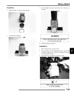
Re-torque both bleeder valves to specification and reinstall
cover caps.
10. Fill reservoir with to a level midway between ‘MAX’ and
‘MIN’ fill lines. Verify no debris is found in reservoir oil.
11. Replace reservoir cap securely and wipe clean any residue.
Disassembly / Inspection
NOTE: see “Gearcase Removal” on page 7.15
1.
Drain and properly dispose of used oil. Remove any metal
particles from the drain plug magnet.
2.
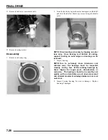
Remove the piston pump assembly from the gearcase.
NOTE: Piston pump assembly is a non-serviceable
item and should not be disassembled. Replace as an
assembly if found to be damaged or non-working.
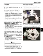
3.
Remove bolts (arrows) retaining the outer cover plate
assembly.
=
T
Bleeder Valve Torque:
80 in. lbs. (9 Nm)
Summary of Contents for Sportsman 800 EFI
Page 4: ...NOTES ...
Page 18: ...NOTES GENERAL INFORMATION 1 14 ...
Page 25: ...2 7 MAINTENANCE 2 LUBRICATION FLUIDS SPORTSMAN Component Locations Sportsman Only Deluxe ...
Page 56: ...2 38 MAINTENANCE Maintenance Schedule Service Date Hours Miles Service Performed Serviced By ...
Page 116: ...NOTES ENGINE 3 60 ...
Page 137: ...4 21 FUEL INJECTION 4 EFI CIRCUIT Power On EFI CIRCUIT Crank Position Sensor ...
Page 138: ...4 22 FUEL INJECTION EFI CIRCUIT Fuel Pump EFI CIRCUIT Throttle Position Sensor ...
Page 140: ...4 24 FUEL INJECTION EFI CIRCUIT Malfunction Indicator Light ...
Page 167: ...5 27 BODY STEERING SUSPENSION 5 X2 CARGO BOX Exploded View ...
Page 170: ...5 30 BODY STEERING SUSPENSION X2 SEAT ASSEMBLY Exploded Views ...
Page 174: ...NOTES BODY STEERING SUSPENSION 5 34 ...
Page 206: ...NOTES CLUTCH SYSTEM 6 32 ...
Page 244: ...7 38 FINAL DRIVE Rear Gearcase Exploded View ...
Page 245: ...TRANSMISSION 8 1 CHAPTER 8 TRANSMISSION 8 SPORTSMAN 8 3 8 18 SPORTSMAN X2 8 19 8 38 ...
Page 246: ...NOTES TRANSMISSION 8 2 ...
Page 248: ...8 4 SPORTSMAN TRANSMISSION TRANSMISSION EXPLODED VIEW Sportsman Transmission ...
Page 265: ...8 21 X2 Touring Transmission 8 242 262 262 262 262 262 ...
Page 266: ...8 22 X2 Touring Transmission Mounting Exploded View x2 x3 x4 x4 x2 x1 x1 x1 ...
Page 312: ...NOTES BRAKES 9 30 ...
Page 322: ...10 10 ELECTRICAL SPEEDOMETER TROUBLESHOOTING Test 1 No All Wheel Drive ...
Page 323: ...10 11 ELECTRICAL 10 TEST 2 No Display TEST 3 No Reverse Speed Limit ...
Page 324: ...10 12 ELECTRICAL TEST 4 No AWD Hub Safety Limiter ...
Page 325: ...10 13 ELECTRICAL 10 TEST 5 Reverse Speed Limiter TEST 6 Speed Sensor ...
Page 326: ...10 14 ELECTRICAL TEST 7 No Fuel Gauge TEST 8 Transmission Switch ...
Page 357: ...10 45 ELECTRICAL 10 BASIC WINCH WIRING PRE WIRED MODELS ...
Page 367: ...10 55 ELECTRICAL 10 Cooling Fan EFI Fuel Pump EFI ...
Page 368: ...10 56 ELECTRICAL Gear Switch EFI Power Circuit EFI ...
Page 369: ...10 57 ELECTRICAL 10 Reverse Override EFI Fan Control EFI ...
Page 370: ...10 58 ELECTRICAL Start Circuit EFI Start Enable EFI ...
Page 373: ...11 3 800 TOURING EFI INTERNATIONAL 11 Exploded View Foot Brake Supply Hand Brake Supply ...
Page 376: ...NOTES 800 TOURING EFI INTERNATIONAL 11 6 ...
Page 382: ...IX 6 Intentional Blank Page ...
Page 383: ...WD 1 WIRE DIAGRAM 2008 SPORTSMAN 800 EFI WIRE DIAGRAM ...
Page 384: ...WD 2 WIRE DIAGRAM ...
Page 385: ...WD 3 WIRE DIAGRAM 2008 SPORTSMAN 700 X2 800 TOURING EFI WIRE DIAGRAM ...
Page 386: ...WD 4 WIRE DIAGRAM ...
Page 387: ...WD 5 WIRE DIAGRAM 2008 SPORTSMAN 800 TOURING EFI INTERNATIONAL WIRE DIAGRAM ...
Page 388: ...WD 6 WIRE DIAGRAM ...

