7.31
FINAL DRIVE
7
Service
NOTE: The following procedure applies to BOTH
inner and outer CV joints.
1.
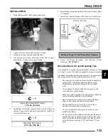
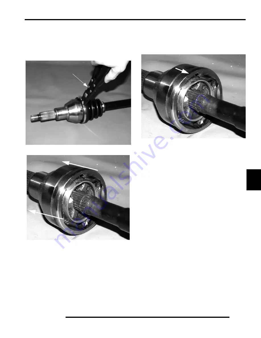
Remove clamps from rubber boot(s) using a CV Boot
Clamp Pliers (A) and slide back boot.
2.
Tap CV housing off shaft with a soft-faced hammer.
3.
Place a new compression ring in the groove of the CV shaft.
4.
Refit CV joint on interconnecting shaft by tapping with a
soft-faced hammer on the joint housing. Take care not to
damage threads on the outboard CV joint. The joint is fully
assembled when the compression ring is seated in the
groove on the CV joint.
5.
Remove excess grease from the CV joint's external surfaces
and position the large boot joint over the CV housing,
making sure boot is seated in groove. Position clamp over
boot end and make sure clamp tabs are located in slots.
6.
Install and tighten large boot clamp with boot clamp pliers.
7.
Remove excess grease from the CV shaft’s external
surfaces and position the small boot joint over the CV shaft,
making sure boot is seated in the shaft groove. While
pulling out on the CV shaft, fully extend the CV joint and
slide a straight O-ring pick or a small slotted screw driver
between the small end of the boot and the shaft. This will
allow the air pressure to equalize in the CV boot in the
position that the joint will spend most of its life. Position
the small clamp over boot end and make sure clamp tabs
are located in slots.
NOTE: Release any air pressure which may have
built up inside the boot has been released. The air
should be released after the joint has been centered
properly.
8.
Tighten small boot clamp using boot clamp pliers.
A
Tap CV housing off shaft
Tap joint onto shaft
Summary of Contents for Sportsman 800 EFI
Page 4: ...NOTES ...
Page 18: ...NOTES GENERAL INFORMATION 1 14 ...
Page 25: ...2 7 MAINTENANCE 2 LUBRICATION FLUIDS SPORTSMAN Component Locations Sportsman Only Deluxe ...
Page 56: ...2 38 MAINTENANCE Maintenance Schedule Service Date Hours Miles Service Performed Serviced By ...
Page 116: ...NOTES ENGINE 3 60 ...
Page 137: ...4 21 FUEL INJECTION 4 EFI CIRCUIT Power On EFI CIRCUIT Crank Position Sensor ...
Page 138: ...4 22 FUEL INJECTION EFI CIRCUIT Fuel Pump EFI CIRCUIT Throttle Position Sensor ...
Page 140: ...4 24 FUEL INJECTION EFI CIRCUIT Malfunction Indicator Light ...
Page 167: ...5 27 BODY STEERING SUSPENSION 5 X2 CARGO BOX Exploded View ...
Page 170: ...5 30 BODY STEERING SUSPENSION X2 SEAT ASSEMBLY Exploded Views ...
Page 174: ...NOTES BODY STEERING SUSPENSION 5 34 ...
Page 206: ...NOTES CLUTCH SYSTEM 6 32 ...
Page 244: ...7 38 FINAL DRIVE Rear Gearcase Exploded View ...
Page 245: ...TRANSMISSION 8 1 CHAPTER 8 TRANSMISSION 8 SPORTSMAN 8 3 8 18 SPORTSMAN X2 8 19 8 38 ...
Page 246: ...NOTES TRANSMISSION 8 2 ...
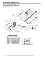
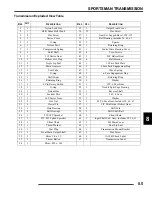
Page 248: ...8 4 SPORTSMAN TRANSMISSION TRANSMISSION EXPLODED VIEW Sportsman Transmission ...
Page 265: ...8 21 X2 Touring Transmission 8 242 262 262 262 262 262 ...
Page 266: ...8 22 X2 Touring Transmission Mounting Exploded View x2 x3 x4 x4 x2 x1 x1 x1 ...
Page 312: ...NOTES BRAKES 9 30 ...
Page 322: ...10 10 ELECTRICAL SPEEDOMETER TROUBLESHOOTING Test 1 No All Wheel Drive ...
Page 323: ...10 11 ELECTRICAL 10 TEST 2 No Display TEST 3 No Reverse Speed Limit ...
Page 324: ...10 12 ELECTRICAL TEST 4 No AWD Hub Safety Limiter ...
Page 325: ...10 13 ELECTRICAL 10 TEST 5 Reverse Speed Limiter TEST 6 Speed Sensor ...
Page 326: ...10 14 ELECTRICAL TEST 7 No Fuel Gauge TEST 8 Transmission Switch ...
Page 357: ...10 45 ELECTRICAL 10 BASIC WINCH WIRING PRE WIRED MODELS ...
Page 367: ...10 55 ELECTRICAL 10 Cooling Fan EFI Fuel Pump EFI ...
Page 368: ...10 56 ELECTRICAL Gear Switch EFI Power Circuit EFI ...
Page 369: ...10 57 ELECTRICAL 10 Reverse Override EFI Fan Control EFI ...
Page 370: ...10 58 ELECTRICAL Start Circuit EFI Start Enable EFI ...
Page 373: ...11 3 800 TOURING EFI INTERNATIONAL 11 Exploded View Foot Brake Supply Hand Brake Supply ...
Page 376: ...NOTES 800 TOURING EFI INTERNATIONAL 11 6 ...
Page 382: ...IX 6 Intentional Blank Page ...
Page 383: ...WD 1 WIRE DIAGRAM 2008 SPORTSMAN 800 EFI WIRE DIAGRAM ...
Page 384: ...WD 2 WIRE DIAGRAM ...
Page 385: ...WD 3 WIRE DIAGRAM 2008 SPORTSMAN 700 X2 800 TOURING EFI WIRE DIAGRAM ...
Page 386: ...WD 4 WIRE DIAGRAM ...
Page 387: ...WD 5 WIRE DIAGRAM 2008 SPORTSMAN 800 TOURING EFI INTERNATIONAL WIRE DIAGRAM ...
Page 388: ...WD 6 WIRE DIAGRAM ...

