background image

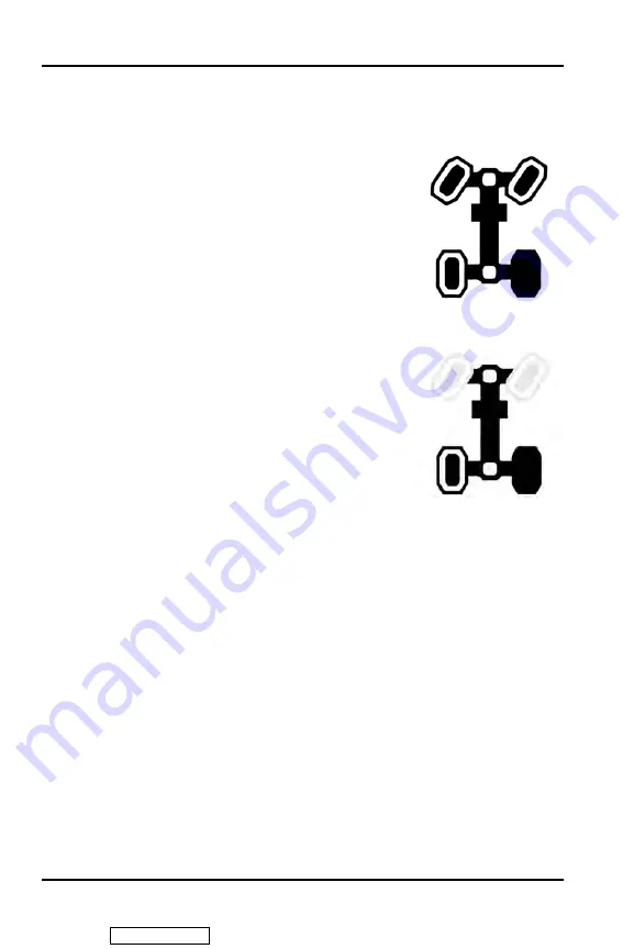
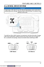
AWD (4X4) MODE

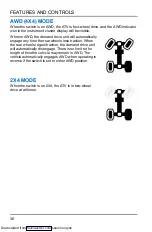
When the switch is on AWD, the ATV is four-wheel drive, and the AWD indicator
icon in the instrument cluster display will be visible.

When in AWD, the demand drive unit will automatically
engage any time the rear wheels lose traction. When
the rear wheels regain traction, the demand drive unit
will automatically disengage. There is no limit to the
length of time the vehicle may remain in AWD. The
vehicle automatically engages AWD when operating in
reverse if the switch is set to either AWD position.

2X4 MODE

When the switch is on 2X4, the ATV is in two-wheel
drive at all times.

38

FEATURES AND CONTROLS

Downloaded from 

ManualsNet.com

 search engine

Summary of Contents for Sportsman 850 2022

Page 1: ... contains important safety information This is an adult vehicle only Operation is prohibited for those under 16 years of age OWNER S MANUAL For Maintenance and Safety Sportsman 850 Sportsman XP 1000 Downloaded from ManualsNet com search engine ...

Page 2: ... service your vehicle in a well ventilated area and wear gloves or wash your hands frequently when servicing your vehicle For more information go to www P65Warnings ca gov passenger vehicle WARNING Read understand and follow all of the instructions and safety precautions in this manual and on all product labels Failure to follow the safety precautions could result in serious injury or death For vi...

Page 3: ...2022 Owner s Manual Sportsman 850 Sportsman 850 Ultimate Trail Sportsman XP 1000 Sportsman XP 1000 LE Sportsman XP 1000 Ultimate Trail Downloaded from ManualsNet com search engine ...
Page 4: ... of HWA Fong Rubber USA Inc DBA Duro Tire Wheel Corp AUTOLITE is a registered trademark of BMO HARRIS BANK N A Tread Lightly is a registered trademark of the United States Department of Agriculture Unless noted trademarks are the property of Polaris Industries Inc Copyright 2021 Polaris Industries Inc All information contained within this publication is based on the latest product information at t...

Page 5: ...r POLARIS vehicle making it the finest machine we ve ever produced For safe and enjoyable operation of your vehicle be sure to follow the instructions and recommendations in this owner s manual Your manual contains instructions for minor maintenance but information about major repairs is outlined in the POLARIS Service Manual and can be performed by a factory certified Master Service Dealer MSD te...

Page 6: ...4 WELCOME Downloaded from ManualsNet com search engine ...

Page 7: ...ures and Controls 31 Operation 67 Winch Guide 87 Emission Control Systems 97 Maintenance 99 Specifications 143 POLARIS Products 159 Troubleshooting 161 Warranty 171 Maintenance Log 179 5 Downloaded from ManualsNet com search engine ...
Page 8: ...6 Downloaded from ManualsNet com search engine ...
Page 9: ...r s manual Understand all safety warnings precautions and operating procedures before operating a POLARIS ATV Keep this manual with the ATV Never operate an ATV without proper instruction Take a certified ATV safety training course In the United States certified training can be found at www atvsafety org This vehicle is an ADULT VEHICLE ONLY Operation is prohibited for anyone under 16 years of age...

Page 10: ...dous situation which if not avoided COULD result in death or serious injury CAUTION CAUTION indicates a hazardous situation which if not avoided COULD result in minor to moderate injury NOTICE NOTICE provides key information by clarifying instructions IMPORTANT IMPORTANT provides key reminders during disassembly assembly and inspection of components The Prohibition Safety Sign indicates an action ...

Page 11: ...number and mating it with one of your existing keys The ignition switch must be replaced if all keys are lost The manufacturer s label is located on the front right side of the vehicle behind the radiator Vehicle Model Number Frame VIN q Engine Serial Number w Key Number REPLACEMENT KEYS A replacement key can be made from the original key Key Blank P N 4080125 Rubber Key Cover P N 5458344 9 INTROD...

Page 12: ...ressly approved by the party responsible for compliance could void the user s authority to operate the equipment CANADA RADIO COMPLIANCE This vehicle contains the following radio equipment or components that contain radio equipment COMPONENT COMPONENT ID MANUFACTURER B1 Gauge Bluetooth LE CYBLE 222014 01 Cypress Semiconductor 9200 Series Display RC 7W Polaris Industries Inc This device contains li...

Page 13: ...contain radio equipment COMPONENT B1 Gauge Bluetooth LE 9200 Series Display COMPONENT ID CYBLE 222014 01 RC 7W MANUFACTURER Cypress Semiconductor Polaris Industries Inc TRANSMITTING FREQUENCY 2402 2480 MHz 2402 2480 MHz MAX RF TRANSMITTING PWR 0 00078 W 0 2432 W Other transmitting radio frequencies may exist outside of EU markets Hereby Polaris Industries Inc declares that the above radio equipmen...

Page 14: ...12 Downloaded from ManualsNet com search engine ...
Page 15: ...ncluded in the purchase price of your ATV You were also provided with printed materials that explain safe operating procedures You should review this information on a regular basis If you purchased a used POLARIS ATV in the United States you can enroll in the ATV RiderCoursesm for a fee Call ATV Enrollment Express at 800 887 2887 or visit www atvsafety org If you purchased a POLARIS ATV outside th...

Page 16: ...l The approval number and serial number will also be displayed on the label EYE PROTECTION Do not depend on eyeglasses or sunglasses for eye protection Whenever riding this POLARIS vehicle always wear shatterproof goggles or use a shatterproof helmet face shield POLARIS recommends wearing approved Personal Protective Equipment PPE bearing markings such as VESC 8 V 8 Z87 1 or CE Make sure protectiv...

Page 17: ... on different types of terrain Beginning and inexperienced operators should complete the recommended safety training before operating this vehicle Never permit a guest to operate the ATV unless the guest has read this manual and all product labels and has completed a certified safety training course AGE RESTRICTIONS This vehicle is an ADULT VEHICLE ONLY Operation is prohibited for anyone under 16 ...

Page 18: ...ce procedures and schedules described in this owner s manual HANDLING GASOLINE Gasoline is highly flammable and explosive under certain conditions Always exercise extreme caution whenever handling gasoline Always refuel with the engine stopped and outdoors or in a well ventilated area Never carry fuel or other flammable liquids on this vehicle Failure to follow this instruction could lead to serio...

Page 19: ...vehicle s tires are designed for off road use only not for use on pavement Operating this vehicle on paved surfaces including sidewalks paths parking lots and driveways may adversely affect the handling of the vehicle and may increase the risk of loss of control and accident or rollover Avoid operating the vehicle on pavement If it s unavoidable travel slowly travel short distances and avoid sudde...

Page 20: ...rmly planted on the footrests they could come into contact with the wheels or other moving parts and lead to accident or injury Always keep both hands on the handlebars and both feet on the footrests of the ATV during operation TURNING IMPROPERLY CAUTION Turning improperly could cause loss of traction loss of control accident or rollover Always follow proper procedures for turning as described in ...

Page 21: ...ENDING HILLS IMPROPERLY Improperly descending a hill could cause loss of control or rollover Always follow proper procedures for traveling down hills as described in this owner s manual See the New Operator Driving Procedures section for details CROSSING HILLSIDES Driving on a sidehill is not recommended Improper procedure could cause loss of control or rollover Avoid crossing the side of any hill...

Page 22: ...e or on the left if the vehicle is pointing straight uphill Have a passenger dismount first then the operator may dismount Turn the ATV around and remount following the procedure described in the owner s manual If the ATV begins rolling downhill Keep operator and passenger body weight uphill Never apply engine power Apply the brake lever gradually When fully stopped apply the auxiliary brake as we...

Page 23: ...excessively rough slippery or loose terrain until you ve learned and practiced the skills necessary to control the vehicle on such terrain Always use extra caution on rough slippery or loose terrain OPERATING IN UNFAMILIAR TERRAIN Failure to use extra caution when operating on unfamiliar terrain could result in an accident or rollover Unfamiliar terrain may contain hidden rocks bumps or holes that...

Page 24: ...g procedures as outlined in this manual See the New Operator Driving Procedures section for details Before shifting into reverse gear always check for obstacles or people behind the vehicle When it s safe to proceed back slowly OPERATING OVER OBSTACLES Improperly operating over obstacles could cause loss of control or rollover Before operating in a new area check for obstacles Avoid operating over...

Page 25: ...ON Operating a damaged vehicle can result in an accident After any rollover or other accident have a qualified service dealer inspect the entire machine for possible damage including but not limited to seat belts rollover protection devices brakes throttle and steering systems OPERATING THROUGH WATER Operating through deep or fast flowing water can cause loss of traction loss of control rollover o...

Page 26: ...gether with any other vehicles in your party Always check with local authorities and residents to confirm ice conditions and thickness over your entire route Vehicle operators assume all risk associated with ice conditions on frozen bodies of water POOR VISIBILITY CAUTION Operating this vehicle in darkness or inclement weather could result in a collision or accident especially if operating on a ro...

Page 27: ...ball receiver and the trailer hitch During operation of the ATV the exhaust will produce hot exhaust gas that should not be inhaled and that may elevate the surface temperature of surrounding surfaces including trailer surfaces e g trailer hitch trailer tongue trailer walls etc To reduce the risk of inhaling exhaust gases and to avoid risk of burn or injury shut off your engine and allow time for ...

Page 28: ...prayers or large racks may change the handling characteristics of the vehicle Use only POLARIS approved accessories and familiarize yourself with their function and effect on the vehicle The addition of certain accessories including but not limited to overhead audio speakers may change the forward clearance in the vehicle Polaris recommends selecting a helmet that is compatible with the equipment ...

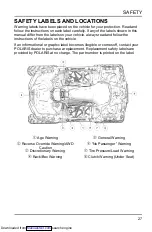
Page 29: ...on the vehicle If an informational or graphic label becomes illegible or comes off contact your POLARIS dealer to purchase a replacement Replacement safety labels are provided by POLARIS at no charge The part number is printed on the label q Age Warning t General Warning w Reverse Override Warning AWD Caution y No Passenger Warning e Discretionary Warning u Tire Pressure Load Warning r Rack Box Wa...

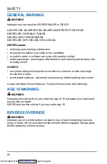
Page 30: ...r riding techniques to avoid vehicle overturns on hills and rough terrain and in turns avoid paved surfaces pavement may seriously affect handling and control Locate and Read Owner s Manual Follow All Instructions And Warnings AGE 16 WARNING WARNING Operating this vehicle if you are under the age of 16 increases your chances of severe injury or death NEVER operate this vehicle if you are under age...

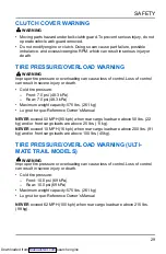
Page 31: ...lbs 261 kg Lug nut torque Reference Owner s Manual NEVER exceed 50 MPH 80 kph when rear cargo loads are above 50 lbs 22 kg and or front cargo loads are above 25 lbs 11 kg NEVER exceed 10 MPH 16 kph when rear cargo loads are above 200 lbs 91 kg and or front cargo loads are above 100 lbs 45 kg TIRE PRESSURE OVERLOAD WARNING ULTI MATE TRAIL MODELS WARNING Improper tire pressure or overloading can cau...

Page 32: ...nd brakes gradually and shift weight uphill REVERSE operation can be dangerous even at low speeds Steering becomes difficult To prevent loss of control avoid sudden braking or sharp turns RACK WARNING FRONT AND REAR WARNING DO NOT TOW FROM RACK OR BUMPER Vehicle damage or tipover may result causing severe injury or death Tow only from tow hooks or hitch Maximum Rack Loads Front 120 lbs 54 kg Rear ...

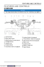
Page 33: ...ode Reverse Override Switch r Headlight Switch t Throttle Lever y Driveline Switch u Drive Mode Switch if equipped i Auxiliary Switch if equipped o Thumb Warmer Switch if equipped a Hand Warmer Switch if equipped s Brake Lever d Auxiliary Outlet f Battery Charge Port g Digital Display 31 FEATURES AND CONTROLS Downloaded from ManualsNet com search engine ...
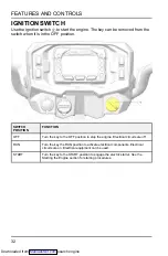
Page 34: ... position to stop the engine Electrical circuits are off RUN Turn the key the RUN position to activate electrical components Electrical circuits are on Electrical equipment can be used START Turn the key to the START position to engage the electric starter See the Starting the Engine section for starting procedures 32 FEATURES AND CONTROLS Downloaded from ManualsNet com search engine ...

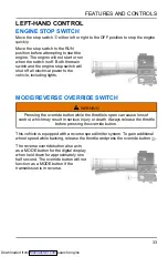
Page 35: ...the override button while the throttle is open can cause loss of control which may result in serious injury or death Always release the throttle before pressing the override button This vehicle is equipped with a reverse speed limiter system To gain additional wheel speed while backing release the throttle and press the override button e The reverse override button also acts as a MODE button for t...

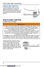
Page 36: ...e system can result in an accident if the throttle lever sticks during operation Always check the lever for free movement and return before starting the engine Also check occasionally during operation Modifications to the electronic throttle control could result in failure to perform as designed which could result in an accident Do not attempt to modify the throttle control system or replace it wi...

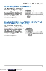
Page 37: ...or more information see page 37 DRIVELINE SWITCH CALIFORNIA HD UTILITY LE AND ULTIMATE TRAIL MODELS On California and Utility models the AWD system is controlled by the AWD Momentary Switch u Use this switch to change the driveline modes between 2WD AWD and AWD ADC The vehicle automatically engages AWD when operating in reverse if the AWD mode is set to AWD For more information see page 37 35 FEAT...

Page 38: ... RPM or at ground speeds below 7 MPH 11 km h PERFORMANCE MODE Offers a more aggressive feel to the power of the vehicle Vehicle will accelerate harder with less throttle movement WORK MODE Throttle is smoother than standard mode Best for when the operator wants more precision over vehicle acceleration This drive mode is recommended to be used when backing up with a trailer driving over rough terra...

Page 39: ...he rear wheels have traction or are at rest The All Wheel Drive AWD system is controlled by the Driveline switch Engage AWD before getting into conditions where front wheel drive may be needed If the rear wheels are spinning release the throttle before switching to AWD AWD Models ADC Models 37 FEATURES AND CONTROLS Downloaded from ManualsNet com search engine ...
Page 40: ...s lose traction When the rear wheels regain traction the demand drive unit will automatically disengage There is no limit to the length of time the vehicle may remain in AWD The vehicle automatically engages AWD when operating in reverse if the switch is set to either AWD position 2X4 MODE When the switch is on 2X4 the ATV is in two wheel drive at all times 38 FEATURES AND CONTROLS Downloaded from...

Page 41: ... AWD remains enabled until the AWD switch is turned off If the switch is turned off while the demand drive unit is moving it will not disengage until the rear wheels regain traction Engage the AWD switch before getting into conditions where front wheel drive may be needed If the rear wheels are spinning release the throttle before switching to AWD NOTICE Switching to AWD or ADC 4X4 while the rear ...

Page 42: ...n or are at rest AWD MODE To engage AWD mode push the momentary switch to the right AWD will engage when engine speed slows to below 3100 RPM The gauge will display AWD There is no limit to the length of time the vehicle may remain in AWD The vehicle automatically engages AWD when operating in reverse if the switch is set to the AWD position Once enabled AWD remains enabled until the switch is tur...

Page 43: ...g a hill ENGAGING ACTIVE DESCENT CONTROL The ADC system will automatically engage when all four of the following conditions occur The 4X4 switch must be in the ADC 4X4 position Vehicle speed must be 15 MPH 25 km h or less The throttle must be closed throttle lever released The transmission must be in gear high low or reverse DISENGAGING ACTIVE DESCENT CONTROL The ADC system will automatically dise...

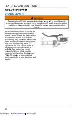
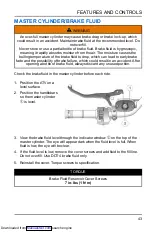
Page 44: ...ont and rear brakes These brakes are hydraulically activated disc type brakes that are activated by only one lever Always test brake lever travel and master cylinder fluid level before riding When squeezed the lever should feel firm Any sponginess would indicate a possible fluid leak or low master cylinder fluid level which must be corrected before riding Contact your POLARIS dealer or other quali...

Page 45: ...ing a bottle of brake fluid always discard any unused portion Check the brake fluid in the master cylinder before each ride 1 Position the ATV on a level surface 2 Position the handlebars so the master cylinder q is level 3 View the brake fluid level through the indicator window w on the top of the master cylinder The eye will appear dark when the fluid level is full When fluid is low the eye will...

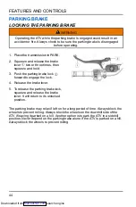
Page 46: ... lock 4 Release the brake lever 5 To release the parking brake lock squeeze and release the brake lever It will return to its unlocked position The parking brake may relax if left on for a long period of time Always block the wheels to prevent rolling Always block the wheels on the downhill side of the ATV if leaving it parked on a hill Another option is to park the ATV in a sidehill position Neve...

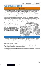
Page 47: ... foot brake squeeze the hand brake simultaneously to prevent tipover The auxiliary foot brake is located on the inside of the right footrest Operate this brake with your right foot If the rear wheels slide while using the auxiliary brake reduce brake pedal pressure to brake the rear wheels without skidding NOTICE Operating a new vehicle or a vehicle with new brake pads requires a break in period t...

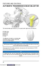
Page 48: ... gear NOTE Shifting gears with the engine speed above idle or while the vehicle is moving could cause transmission damage Whenever the ATV is left unattended always place the transmission in PARK and lock the parking brake TIP To extend belt life use low forward gear when pulling a heavy load at less than seven miles per hour for extended periods and when operating uphill at a slow speed 46 FEATUR...

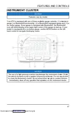
Page 49: ...he gauge at start up If your model is equipped with a no button gauge use the MODE button on the left hand control to navigate the display menu NOTICE The use of a high pressure washer may damage the instrument cluster Wash the vehicle by hand or with a garden hose using mild soap Do not use alcohol to clean the instrument cluster Do not allow insect sprays to contact the lens Immediately clean of...

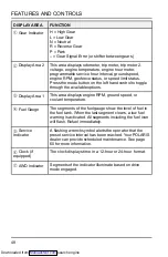
Page 50: ...RPM ground speed or coolant temperature r Fuel Gauge The segments of the fuel gauge show the level of fuel in the fuel tank When the last segment clears a low fuel warning is activated All segments including the fuel icon will flash Refuel immediately t Service Indicator A flashing wrench symbol alerts the operator that the preset service interval has been reached Your POLARIS dealer can provide s...

Page 51: ...h key on engine off for up to 5 minutes Engine Hot This lamp illuminates to indicate an overheated engine If the indicator flashes a severe overheating condition exists Neutral This lamp illuminates when the transmission is in neutral and the ignition key is in the ON position Helmet Seat Belt This lamp flashes for several seconds when the key is turned to the ON position The lamp is a reminder to...

Page 52: ...ped with a low speed limiter indicator light will remain on when low speed limiter is active Lamp illuminates when Geofencing or max speed is enabled Lamp remains off when Geofencing and max speed settings are disabled 50 FEATURES AND CONTROLS Downloaded from ManualsNet com search engine ...
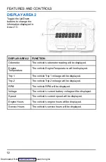
Page 53: ...n Area 1 q DISPLAY AREA 1 FUNCTION Speed The vehicle s speed will be displayed in mph or km h Engine Temperature The vehicle s current engine temperature will be displayed RPM The vehicle s RPM will be displayed 51 FEATURES AND CONTROLS Downloaded from ManualsNet com search engine ...
Page 54: ...ip 1 The vehicle Trip 1 mileage will be displayed Trip 2 The vehicle Trip 2 mileage will be displayed RPM The vehicle RPM will be displayed Voltage The vehicle s current battery voltage will be displayed Speed The vehicle s current speed will be displayed Engine Hours The vehicle s engine hours will be displayed Service Hours The vehicle s service hours will be displayed 52 FEATURES AND CONTROLS D...

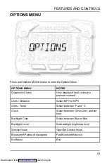
Page 55: ...stance Select MPH or KPH Units Temp Select between F and C Clock Select between 12H or 24H and set time Backlight Color Select between Blue or Red Backlight Level Set backlight brightness level Service Hours View Set Service hours Bluetooth Pairing if equipped Pair Bluetooth device Exit Menu Exit 53 FEATURES AND CONTROLS Downloaded from ManualsNet com search engine ...
Page 56: ... menu item 2 Select Diagnostic Codes from the Options Menu by pressing the MODE button Toggle the Up Down Buttons to cycle through Code s NOTICE This option will only be available if a fault code was set or is active during the current ignition key on cycle Turning off the ignition will clear any save fault codes from the gauge q Display area 1 will show FMI w Display area 2 will show SPN e Clock ...

Page 57: ...NS will display on the screen for 3 seconds before showing first menu item 2 Select Units Distance from the Options Menu by pressing the MODE button Reference the image shown above q Press the MODE button w Toggle the Up Down Buttons to change the units MPH or KPH e With the correct unit displayed Press the mode button which will set the unit and return to the Options Menu 3 To exit the Options Me...

Page 58: ...e q Press the MODE button w Toggle the Up Down Buttons to change the units F or C e With the correct unit displayed Press the mode button which will set the unit and return to the Options Menu 3 To exit the Options Menu the user can select Exit Menu function from Options Menu can hold Mode Button and exit out of Options Menu or not press any button for 10 seconds which will exit out of the Options...

Page 59: ...ith the correct unit displayed Press the mode button which will set the unit y Toggle the Up Down Buttons to change the units Cycles 10s of Minutes u With the correct unit displayed Press the mode button which will set the unit i Toggle the Up Down Buttons to change the units Cycles 1s of Minutes o With the correct unit displayed Press the mode button which will set the unit and return to the Opti...

Page 60: ...ress the MODE button w Toggle the Up Down Buttons to change the units Blue or Red e With the correct unit displayed Press the mode button which will set the unit and return to the Options Menu 3 To exit the Options Menu the user can select Exit Menu function from Options Menu can hold Mode Button and exit out of Options Menu or not press any button for 10 seconds which will exit out of the Options...

Page 61: ... MODE button w Toggle the Up Down Buttons to change the units Increase or De crease Level e With the correct unit displayed Press the mode button which will set the unit and return to the Options Menu 3 To exit the Options Menu the user can select Exit Menu function from Options Menu can hold Mode Button and exit out of Options Menu or not press any button for 10 seconds which will exit out of the...

Page 62: ...5 10 95 100 e With the correct unit displayed press the MODE button which will set the unit and return you to the Options Menu NOTICE To reset service hours after they have counted down to 0 0 reselect the existing setpoint or select a new service hour value 3 To exit the Options Menu the user can select Exit Menu function from Options Menu can hold Mode Button and exit out of Options Menu or not ...

Page 63: ...hone with the vehicle s digital gauge NOTICE Bluetooth functionality is compatible with both iOS and Android phones For iOS phones you must go to the Settings option and enable notifications Most Android phones will prompt the user automatically to enable notifications as part of the pairing process 1 Make sure Bluetooth is enabled on your phone 2 Access the options menu on the vehicle s digital g...

Page 64: ...tion Refuel when the gauge indicates a low fuel condition Always refuel with the engine stopped and outdoors or in a well ventilated area Refuel on a level surface Remove the fuel tank cap to add fuel to the fuel tank Use only unleaded gasoline with a minimum pump octane number of 87 R M 2 octane Do not use fuel with ethanol content greater than 10 percent such as E 85 fuel 62 FEATURES AND CONTROL...

Page 65: ... EPS mode do the following 1 Stop the ATV and put it in PARK 2 Press and hold the MODE button to enter the Options Menu OPTIONS will display on the screen for 3 seconds before showing the first menu item 3 Select EPS from the Options Menu by pressing the MODE button 4 Toggle the Up Down Buttons to choose between the high medium and low modes 5 Press the MODE button to lock in the EPS setting BATTE...

Page 66: ...d battery is inadequate due to operation in extreme cold or due to extended use of multiple electrical accessories your POLARIS dealer can assist Your dealer can provide any installation procedures that may differ for an extreme use battery FRONT COMPARTMENT 64 FEATURES AND CONTROLS Downloaded from ManualsNet com search engine ...
Page 67: ...e Relay w Radiator Cap r Battery FRONT RACK If your model is equipped with front compartment storage unlock both latches on each side and remove the cover to gain access 65 FEATURES AND CONTROLS Downloaded from ManualsNet com search engine ...

Page 68: ...66 Downloaded from ManualsNet com search engine ...
Page 69: ...iary brake for emergency situations if service brakes become inoperable 6 Operate this vehicle off road only Never operate the vehicle on pavement or on any public street road or highway including dirt and gravel roads 7 Use caution and drive at reduced speeds in conditions of reduced visibility such as fog rain and darkness Clean headlights frequently and replace burned out headlamps promptly 8 D...

Page 70: ...g areas are by contacting your POLARIS dealer a local riding club or local officials Help keep our trails open for recreational vehicle use As an off road enthusiast you represent the sport and can set a good example or a poor example for others to follow Tread lightly Operate with respect for the terrain avoid littering and always stay on the designated trails VEHICLE BREAK IN PERIOD The break in...

Page 71: ... 250 miles 9 Check fluid levels of transmission and all gearcases after the first 25 hours of operation and every 100 hours thereafter BRAKE SYSTEM BREAK IN Apply only moderate braking force for the first 50 stops Aggressive or overly forceful braking when the brake system is new could damage brake pads and rotors PVT BREAK IN CLUTCHES BELT Always break in the clutches and drive belt of new vehicl...

Page 72: ...necessary Steering Ensure free operation Tires Inspect condition and pressure page 116 Wheels fasteners Inspect ensure fastener tightness Frame nuts bolts fasteners Inspect ensure tightness Fuel and oil Ensure proper levels page 105 Coolant level Ensure proper level page 113 Coolant hoses Inspect for leaks Throttle Ensure proper operation page 34 Indicator lights switches Ensure operation page 49 ...

Page 73: ...ansmission in PARK 4 Lock the brake holding latch 5 Mount the vehicle from the left side 6 Sit upright with both feet on the footrests and both hands on the handlebars 7 Start the engine and allow it to warm up 8 Shift the transmission into gear 9 Check your surroundings and determine your path of travel 10 Release the brake holding latch 11 Slowly depress the throttle with your right thumb and be...

Page 74: ... 5 Lean your upper body to the inside of the turn while supporting your weight on the outer footrest This technique alters the balance of traction between the rear wheels allowing the turn to be made smoothly The same leaning technique should be used for turning in reverse 6 Practice making turns at slow speeds before attempting to turn at faster speeds WARNING Turning improperly can result in veh...

Page 75: ...not operate on excessively rough slippery or loose terrain 2 Slow down when entering slippery areas 3 Engage 4X4 before wheels begin to lose traction NOTICE Severe damage to drive train may occur if the 4X4 is engaged while the wheels are spinning Allow the rear wheels to stop spinning before engaging 4X4 or engage 4X4 before wheels begin to lose traction 4 Maintain a high level of alertness readi...

Page 76: ...ing any hill 5 Never climb hills with excessively slippery or loose surfaces 6 Keep both feet on the footrests 7 Shift body weight uphill 8 Proceed at a steady rate of speed and throttle opening Opening the throttle suddenly could cause the ATV to flip over backwards 9 Never go over the top of any hill at high speed An obstacle a sharp drop or another vehicle or person could be on the other side o...

Page 77: ...in forward gear Do not descend a hill with the transmission in neutral 5 Slow down Never travel down a hill at high speed 6 Drive straight downhill Avoid traveling down a hill at an angle which would cause the vehicle to lean sharply to one side 7 Shift body weight uphill 8 Apply the brakes slightly to aid in slowing Applying the brakes too firmly may cause the rear wheels to lock which could resu...

Page 78: ...ssing a sidehill is unavoidable follow these precautions 1 Slow down 2 Avoid crossing the side of a steep hill 3 Lean into the hill transferring your upper body weight toward the hill while keeping your feet on the footrests 4 If the vehicle begins to tip quickly turn the front wheel downhill if possible or dismount on the uphill side immediately 76 OPERATION Downloaded from ManualsNet com search ...

Page 79: ...r on the left if the vehicle is pointing straight uphill 5 Staying uphill of the vehicle turn the handlebars full left 6 While holding the brake lever release the parking brake lock and slowly allow the vehicle to roll around to your right until it s pointing across the hill or slightly downward 7 Lock the parking brake Remount the vehicle from the uphill side keeping body weight uphill Start the ...

Page 80: ...al and take the vehicle in for service at the first opportunity Your ATV can operate through water with a maximum recommended depth equal to the bottom of the footrests Follow these procedures when operating through water 1 Determine water depths and current before entering water 2 Choose a crossing where both banks have gradual inclines 3 Avoid operating through deep or fast flowing water 4 After...

Page 81: ...as logs rocks and low hanging branches 3 Travel slowly and use extra caution when operating on unfamiliar terrain Not all obstacles are immediately visible 4 Never attempt to operate over large obstacles such as rocks or fallen trees 5 Always have a passenger dismount before operating over an obstacle that could cause a fall from the vehicle or vehicle tipover 79 OPERATION Downloaded from ManualsN...

Page 82: ...7 Do not use the override switch unless additional wheel speed is required for vehicle movement Use the override with caution as rearward vehicle speed is greatly increased Do not operate at wide open throttle Operate the throttle just enough to maintain a desired speed NOTICE Excessive throttle operation while in the speed limit mode may cause fuel to build in the exhaust resulting in engine popp...

Page 83: ...the key to the OFF position and wait five seconds before attempting to start again Activate the starter for another five seconds if necessary Repeat this procedure until the engine starts NOTICE Operating the vehicle immediately after starting could cause engine damage Allow the engine to warm up for several minutes before operating the vehicle COLD WEATHER OPERATION If the vehicle is used year ro...

Page 84: ...nly and firmly Practice starting and stopping using the brakes until you re familiar with the controls PARKING THE VEHICLE 1 Stop the vehicle on a level surface When parking inside a garage or other structure be sure that the structure is well ventilated and that the vehicle is not close to any source of flame or sparks including any appliance with pilot lights 2 Place the transmission in PARK 3 T...

Page 85: ...ht of the operator accessories loads in the rack or box and the load on the trailer tongue The combined weight of these items must not exceed the maximum weight capacity CARGO WEIGHT DISTRIBUTION should be 1 3 on the front rack and 2 3 on the rear rack When operating over rough or hilly terrain reduce speed and cargo to maintain stable driving conditions Carrying loads on only one rack increases t...

Page 86: ...hen towing loads in rough terrain while cornering or while ascending or descending a hill HAULING CARGO GUIDELINES 1 Never exceed the weight capacities specified for your ATV on warning labels and in the specifications section of this manual 2 Cargo weight should be evenly distributed 1 3 on the front rack and 2 3 on the rear rack and mounted as low as possible 3 When operating over rough or hilly...

Page 87: ...nty Never install a hitch longer than 4 10 cm Never install automotive accessories on your POLARIS ATV Always install POLARIS approved or equivalent accessories designed for ATV use MAXIMUM TOWING CAPACITIES Do not exceed maximum towing capacities Avoid towing on inclines 850 MODELS XP 1000 MODELS Maximum Towed Load Level Ground 1500 lbs 680 kg 1500 lbs 680 kg Maximum Vertical Hitch Weight 150 lbs...

Page 88: ...RK 3 Secure the fuel cap oil cap and seat 4 Remove the key to prevent loss during transporting 5 Use suitable straps or rope to secure the vehicle to the front tow hook q and rear tow bracket w Do not attach tie straps to the front A arm bolt pockets racks or handlebars 86 OPERATION Downloaded from ManualsNet com search engine ...
Page 89: ... and hook when operating winch 6 Never attempt to jerk a load attached to the winch with a moving vehicle See the Shock Loading section on page 95 7 Always keep the area around the vehicle winch winch cable and load clear of people especially children and distractions while operating the winch 8 Always turn the vehicle ignition power OFF when it and the winch are not being used 9 Always be sure th...

Page 90: ...alls during operation stop winching and permit the winch to cool down for 10 minutes before using it again 16 Never touch push pull or straddle the winch cable while winching a load 17 Never let the winch cable run through your hands even if wearing heavy gloves 18 Never release the clutch on the winch when the winch cable is under load 19 Never use the winch for lifting or transporting people 20 ...

Page 91: ...hat your winch is very powerful There are simply some situations that you and your winch will not be able to deal with Do not be afraid to ask others to help when this happens 1 Always inspect the vehicle winch winch cable and winch controls for any signs of damage or parts in need of repair or replacement before each use Pay particular attention to the first 3 feet 1 meter of winch cable if the w...

Page 92: ...nch cable breaks This can result in SEVERE INJURY or DEATH See the Shock Loading section on page 95 Never hook the winch cable back onto itself This will damage the winch cable and may result in winch cable failure WARNING Replace the winch cable at the first sign of damage to prevent SEVERE INJURY or DEATH in the event of failure For your safety always replace POLARIS winch parts including the ca...

Page 93: ...tch and pull out the winch cable 7 Pulling out as much cable as possible maximizes the winch s pulling capacity Always be sure that at least five 5 full turns of winch cable are wrapped around the winch drum at all times The friction provided by this wrapped cable allows the drum to pull on the winch cable and move the load 8 Read and adhere to the following information for winch damping to ensure...

Page 94: ...e free a Release the winch clutch and spool out the necessary length of winch cable b Align the winch cable as close as possible to the winching vehicle s centerline c Attach the winch cable hook to the anchor point or the stuck vehicle s frame following instructions in this manual d Re engage the clutch on the winch e Slowly winch in the slack in the winch cable f Select the proper vehicle gear t...

Page 95: ...le it may be necessary to re distribute the winch cable across the winch drum You will need an assistant to perform this task a Release the clutch on the winch b Feed out the winch cable that is unevenly bunched up in one area c Re engage the winch clutch d Have an assistant pull the winch cable tightly with about 100 lbs 45 kg of tension using the hook strap e Slowly winch the cable in while your...

Page 96: ... been permanently and severely damaged Promptly discontinue use of a winch cable in this condition A kinked winch cable made of wire rope that has been straightened out is shown at right Even though it may look usable the cable has been permanently and severely damaged It can no longer transmit the load that it could prior to kinking Promptly discontinue use of a winch cable in this condition A wi...

Page 97: ... winch cable and generates excessive heat from the motor This is a form of shock loading 3 Never tow a vehicle or other object with your winch Towing an object with a winch produces shock loading of the cable even when towing at slow speeds Towing from a winch also positions the towing force high on the vehicle This can cause instability of the vehicle and possibly lead to an accident 4 Never use ...

Page 98: ...place POLARIS winch parts including the cable with genuine POLARIS replacement parts available at your authorized POLARIS dealer or other qualified person 5 Some winch models use wire rope as the winch cable Other winches use a specially designed synthetic rope as the winch cable 6 Never replace a synthetic rope winch cable with a consumer grade polymer rope such as can be purchased in a hardware ...

Page 99: ...with a closed crankcase system Blow by gases are forced back to the combustion chamber by the intake system All exhaust gases exit through the exhaust system EXHAUST EMISSION CONTROL SYSTEM Exhaust emissions are controlled by engine design An electronic fuel injection EFI system controls fuel delivery The engine and EFI components are set at the factory for optimal performance and are not adjustab...

Page 100: ...98 Downloaded from ManualsNet com search engine ...
Page 101: ...nt parts may be used for emissions related service Record maintenance and service in the Maintenance Log beginning on page 179 Service and adjustments are important for proper vehicle operation If you re not familiar with safe service and adjustment procedures a qualified dealer can perform these operations Maintenance intervals in the following chart are based upon average riding conditions and a...

Page 102: ... Record maintenance and service in the Maintenance Log ITEM MAINTENANCE INTERVAL WHICHEVER COMES FIRST REMARKS HOUR S CALENDAR MILES KM Steering Pre Ride Inspect and make adjustments as needed Front Suspension Rear Suspension Tires Brake Fluid Level Brake Lever Travel Brake System Wheels Fasteners CV Boot Frame Fasteners Engine Oil Level Winch if equipped XU Air Filter Pre Filter Daily Inspect cle...

Page 103: ...k XU General Lubrication 50 H 3 M 500 800 Lubricate all fittings pivots cables etc Shift Linkage 50 H 3 M 500 800 Inspect D Steering 50 H 6 M 500 800 Lubricate XU Front Rear Suspension 50 H 6 M 500 800 Lubricate XU Throttle Release Switch 50 H 6 M 500 800 Inspect adjust lubricate replace if necessary Throttle Body Intake Duct 50 H 6 M 500 800 Inspect ducts for proper sealing air leaks Drive Belt 5...

Page 104: ... 600 1000 Inspect replace as needed XU Wiring 100 H 12 M 1000 1600 Inspect for wear routing security apply dielectric grease to connectors subjected to water mud etc D Clutches Drive Driven 100 H 12 M 1000 1600 Inspect clean replace worn parts D Wheel Bearings 100 H 12 M 1000 1600 Inspect replace as needed D Brake Fluid 200 H 24 M 2000 3200 Change every two years Spark Arrestor 300 H 36 M 3000 480...

Page 105: ...50 4 Cycle Oil 2 qt 1 9 l 12 ft lbs 16 Nm page 104 Transmission Oil AGL Gearcase Lubricant Transmission Fluid 37 oz 1100 ml 14 ft lbs 19 Nm 14 ft lbs 19 Nm page 108 Demand Drive Fluid Front Gearcase Demand Drive Fluid 9 3 oz 275 ml 19 ft lbs 26 Nm 19 ft lbs 26 Nm page 110 Rear Gearcase Oil ATV Angle Drive Fluid or GL5 80 90 weight gear lube 7 1 oz 210 ml 12 ft lbs 16 Nm 12 ft lbs 16 Nm page 111 Br...

Page 106: ...ccelerated wear and may result in engine seizure accident and injury Always perform the maintenance procedures as outlined in the Periodic Maintenance Chart OIL RECOMMENDATIONS Always change the oil filter whenever changing oil POLARIS recommends the use of POLARIS PS 4 Full Synthetic 5W 50 4 cycle oil or a similar oil for this engine Oil may need to be changed more frequently if POLARIS oil is no...

Page 107: ... the left side of the ATV q Remove the dipstick Wipe it dry with a clean cloth 3 Reinstall and tighten the dipstick 4 Remove the dipstick and check the oil level 5 Add the recommended fluid as needed Maintain the oil level in the safe range between the FULL and ADD marks Do not overfill 6 Reinstall and tighten the dipstick 105 MAINTENANCE Downloaded from ManualsNet com search engine ...

Page 108: ... idle for two to three minutes 3 Stop the engine 4 Clean the area around the drain plug 5 Place a drain pan under the crankcase 6 Remove the drain plug Allow the oil to drain completely CAUTION Hot oil can cause burns to skin Do not allow hot oil to contact skin 7 Install a new sealing washer on the drain plug The sealing surfaces on drain plug and crankcase should be clean and free of burrs nicks...

Page 109: ...good condition 13 Install the new filter and rotate it clockwise by hand until the filter gasket contacts the sealing surface then turn it an additional 1 2 turn 14 Remove the dipstick Add the proper amount of the recommended oil Do not overfill 15 Reinstall the dipstick 16 Place the transmission in PARK 17 Lock the parking brake 18 Start the engine Allow it to idle for one to two minutes 19 Stop ...

Page 110: ... the gearcase OIL CHECK 1 Remove the fill plug Check the oil level 2 Add the recommended fluid as needed to bring the level to the bottom of the fill hole threads 3 Reinstall the fill plug Torque to specification TORQUE Fill Plug 14 ft lbs 19 N m 4 Reinstall the footwell OIL CHANGE 1 Place a drain pan under the gearcase Remove the drain plug Allow the oil to drain completely 2 Clean and reinstall ...

Page 111: ...all the fill plug Torque to specification TORQUE Fill Plug 14 ft lbs 19 N m 5 Check for leaks 6 Reinstall the footwell 7 Dispose of used oil properly 109 MAINTENANCE Downloaded from ManualsNet com search engine ...
Page 112: ...for service Use the recommended fluid Use of other fluids may result in improper operation of components Maintain the fluid level at the bottom of the fill hole threads The fill plug is located on the right side of the demand drive unit The drain plug is located on the bottom right side of the unit FLUID CHECK 1 Position the vehicle on a level surface Remove the fill plug q Check the fluid level 2...

Page 113: ...t See page 159 for the part numbers of POLARIS products The fill plug is located on the rear of the gearcase The drain plug is located on the bottom of the gearcase Maintain the fluid level at the bottom of the fill hole threads Do not overfill OIL CHECK 1 Position the vehicle on a level surface 2 Remove the fill plug q Check the oil level 3 Add the recommended oil as needed to bring the level to ...

Page 114: ... to specification TORQUE Fill Plug 12 in lbs 16 7 Check for leaks 8 Dispose of used oil properly POWER STEERING UNIT IF EQUIPPED If your model is equipped with power steering frequently clean the areas around and on the power steering unit to allow proper cooling Clean these areas e thoroughly STEERING ASSEMBLY The steering assembly of the ATV should be checked periodically for loose nuts and bolt...

Page 115: ...for the part numbers RECOVERY BOTTLE COOLANT The recovery bottle fluid level can be viewed from inside the front right wheel well Access the recovery bottle cap under the front box 1 View the fluid level in the bottle 2 If the level is low remove the bottle cap and add coolant as needed Maintain the coolant level between the minimum and maximum marks on the bottle when the fluid is cool 3 Reinstal...

Page 116: ...slowly add coolant through the radiator filler neck 4 Reinstall the pressure cap Use of a non standard pressure cap will not allow the recovery system to function properly Your POLARIS dealer can provide the correct replacement part 5 Close and secure the front box and cover 114 MAINTENANCE Downloaded from ManualsNet com search engine ...
Page 117: ...heavily under normal operation 1 Always keep brake fluid at an adequate level See the Master Cylinder Brake Fluid section for details 2 Check the brake system for fluid leaks 3 Check the brakes for excessive travel or spongy feel 4 Check the friction pads for wear damage and looseness Replace brake pads when they are worn to 030 0 762 mm 5 Check the security and surface condition of the disc Clean...

Page 118: ...n the vehicle Always use original equipment size and type when replacing tires Refer to the specifications section for recommended tire type size and pressure TIRE TREAD DEPTH Always replace tires when tread depth is worn to 3 mm 1 8 or less FRONT WHEEL HUB TIGHTENING Front wheel bearing tightness and spindle nut retention are critical component operations All service must be performed by your aut...

Page 119: ...ng brake 3 Place the wheel on the hub with the valve stem toward the outside and rotation arrows on the tire pointing toward forward rotation if equipped 4 Install the wheel nuts and finger tighten them 5 Lower the vehicle to the ground 6 Torque the wheel nuts to specification WARNING Loose nuts could cause a tire to come off during operation which could result in an accident or overturn Always en...

Page 120: ...urface 2 Place the handlebars in a straight ahead position 3 Tie a length of string between two stands Position the stands so that the string is flush with the side of the rear tire If available you may use a long straight edge instead of string 4 Measure the distance from the string to the rim at the front q and rear w of the front rim The rear measurement should be 1 8 1 4 inch 3 6 mm more than ...

Page 121: ...e seat FUSE REPLACEMENT If the engine stops or will not start or if you experience other electrical failures a fuse may need replacement Locate and correct any short circuits that may have caused the blown fuse then replace the fuse Spare fuses are provided in the fuse box 1 Access the fuses under the front box 2 Remove the fuse box cover 3 Remove the suspect fuse from the fuse panel If the fuse i...

Page 122: ...t with denatured alcohol CAUTION Hot components can cause burns to skin Allow lamps to cool before servicing 1 Remove the four 4 headlight pod screws Pull the pod cover forward 2 Unplug the headlamp from the wiring harness Be sure to pull on the connector not on the wiring 3 Turn the lamp counter clockwise to remove it 4 Install the new lamp Make sure the tab on the lamp locates properly in the ho...

Page 123: ...eadlight and make a mark on the wall at the same height 3 Start the engine Turn the headlight switch to high beam 4 Observe the headlight aim on the wall The most intense part of the headlight beam should be 2 in 5 cm below the mark on the wallw Include rider weight on the seat when measuring 5 The adjustment screw is located on the left side of the headlight pod To adjust the beam loosen the scre...

Page 124: ...to high beam 5 Observe the headlight aim on the wall The most intense part of the headlight beam should be aimed 2 in 5 cm below the mark placed on the wall in Step 3 6 Open the front rack 7 Adjust the beam to desired position and tightening or loosening the screws at the top of the lights Adjust each light independently WARNING Due to the nature of ATVs and where they are operated headlight lense...

Page 125: ...g and reassemble the pod LOWER HEADLAMP REPLACEMENT 1 Turn the back of the headlight harness counter clockwise and pull the harness assembly away from the headlight assembly 2 Remove the headlamp and install the new headlamp 3 Reinstall the harness assembly into the headlight assembly NOTE Take care to avoid touching the glass on the new headlight bulb Fingerprints on the glass may result in prema...

Page 126: ... assembly 3 Remove the 3 fasteners securing the light assembly and then remove the assembly 4 Install the new light assembly then re affix and tighten the 3 fasteners 5 Reinstall the harness connector 6 Reinstall the heat shield 7 Test the light for proper operation TO REPLACE CENTER TAILLIGHT 1 Remove the rear rack and rear storage box 2 Remove the harness connector from the back of the light ass...

Page 127: ...iately check the spark plug for correct color CAUTION A hot exhaust system and engine can cause burns Wear protective gloves when removing a spark plug for inspection Allow engine to cool before removing spark plug wire 1 Rotate the spark plug cap 1 4 turn and pull it off the spark plug 2 Rotate the spark plug counter clockwise to remove it 3 Reverse the procedure for spark plug installation Torqu...

Page 128: ...he filter with a new filter If equipped remove the air box drain plug q to drain water Reinstall the drain plug Make sure the E ring is on the drain plug and reinstall the drain plug NOTICE Serious damage could occur if the air box drain plug is not reinstalled and tightened properly 3 Remove the spark plugs 4 Turn the engine over several times using the electric start 5 Dry the spark plugs Reinst...

Page 129: ...t stand behind or in front of the vehicle while purging the exhaust system Never go under the vehicle while it is inclined Wear eye protection and gloves while servicing Periodically clean the spark arrestor to remove accumulated carbon 1 Place the transmission in PARK 2 Remove the arrestor retaining bolt and nut 3 Remove the arrestor from the end of the muffler 4 Use non synthetic brush to clean ...

Page 130: ...e during operation The basic operation of the POLARIS PVTsystem is dependent on engine speed and vehicle torque requirements As engine speed increases the force exerted on the movable drive sheave by the flyweights also increases This in turn increases the amount of pinch applied to the drive belt Similarly if the engine speed decreases the amount of centrifugal force decreases reducing the amount...

Page 131: ...y ingested into the PVT system Use the following instructions to dry it out before operating 1 Position the vehicle on a level surface 2 Remove the drain plug Allow the water to drain completely Reinstall the drain plug 3 Start the engine Place the transmission in PARK 4 Apply varying throttle for 10 15 seconds to expel the moisture and air dry the belt and clutches Do not hold the throttle wide o...

Page 132: ...corrosion If cleaning is necessary remove corrosion with a stiff wire brush Wash with a solution of one tablespoon baking soda and one cup water Rinse well with tap water and dry off with clean shop towels Coat the terminals with dielectric grease or petroleum jelly BATTERY REMOVAL 1 Access the battery under the front box 2 Disconnect the black negative battery cable first 3 Disconnect the red pos...

Page 133: ...n in a cool dry place Check battery voltage each month during storage and recharge as needed to maintain a full charge POLARIS recommends maintaining battery charge by using a POLARIS Battery Tender charger or by charging about once a month to make up for normal self discharge Battery Tender can be left connected during the storage period and will automatically charge the battery if the voltage dr...

Page 134: ...facturer s instructions for recharging When using a constant current charger use the following guidelines via the table below BATTERY CHARGING Always verify battery condition before and 1 2 hours after the end of charging STATE OF CHARGE VOLTAGE ACTION CHARGE TIME USING CONSTANT CURRENT CHARGER STANDARD AMPS SPECIFIED ON TOP OF BATTERY 100 12 6 12 8 volts Low Maintenance Battery check after 60 day...

Page 135: ...ORV models include either a Conventional battery or a Low Maintenance battery CONVENTIONAL BATTERY The battery is NOTactivated when packaged Distilled water and electrolyte added as required Removable cap plugs located on top of battery Vent tube located on side of battery LOW MAINTENANCE BATTERY Battery activated when packaged Distilled water and electrolyte NEVER added Non removable cap s locate...

Page 136: ...back onto the battery The gas pressure can cause the battery to rupture Let the battery sit for 30 minutes after you add the initial electrolyte Once absorbed fill the battery with additional electrolyte to the upper line of the electrolyte level indicator This is the only time that electrolyte should be added to the battery Once the battery is fully charged replace cap plugs by hand Do NOT use a ...

Page 137: ...the battery Keep the electrolyte container in place for 20 minutes or longer until the container is completely empty If necessary gently tap the container to empty it Once the battery is fully charged replace the strip of caps by hand Do NOT use a tool to install the strip CHARGING Polaris recommends using a BatteryMINDer 2012 AGM 2 AMP PN 2830438 charger which can be ordered through your normal p...

Page 138: ...ll potential Nominal voltage is 12 6 to 12 8 Volts when fully charged If the voltage falls below 12 5V charge it immediately or the battery service life and vehicle performance may be affected Polaris recommends using a BatteryMINDer 12V 1 5 AMP Convertible PN 2830511 charger or a similar charger which can be ordered through your normal parts channel Charge the battery with a charging output no la...

Page 139: ...AGM 2 AMP PN 2830438 charger If you plan to store the vehicle for ONE month or longer remove the battery from the vehicle and store the battery in a cool dry location Continue to maintain the battery with the BatteryMINDer 2012 AGM 2 AMP PN 2830438 charger and inspect the battery every 60 days TESTING If the test fails fully charge the battery If the battery is too low to accept a charge see the A...

Page 140: ... POLARIS dealer for service 1 Remove the upper headlight pod 2 Loosen the four handlebar bolts 3 Adjust the handlebar to the desired height Be sure the handlebars do not contact the gas tank or any other part of the machine when turned fully to the left or right 4 Torque the front two bolts to specification then torque the rear two bolts A gap of up to 1 8 3 mm will remain at the rear of the clamp...

Page 141: ...s If an informational or graphic label becomes illegible or comes off contact your POLARIS dealer to purchase a replacement Replacement safety labels are provided by POLARIS at no charge Grease all zerk fittings immediately after washing Allow the engine to run for a while to evaporate any water that may have entered the engine or exhaust system WASHING TIPS Avoid the use of harsh cleaners which c...

Page 142: ... Clean Fuel Treatment or POLARIS Fuel Stabilizer or equivalent fuel treatments or stabilizers Follow the instructions on the container for the recommended amount Carbon Clean removes water from fuel systems stabilizes fuel and removes carbon deposits from pistons rings valves and exhaust systems 3 Allow the engine to run for 15 20 minutes to allow the stabilizer to disperse through the entire fuel...

Page 143: ...vities into the hole at the front of the cylinder head and appear to be an oil leak 3 Reinstall the spark plugs Torque to specification 4 Apply dielectric grease to the inside of each spark plug cap Do not reinstall the cap onto the plug at this step 5 Turn the engine over several times Oil will be forced in and around the piston rings and ring lands coating the cylinder with a protective film of ...

Page 144: ...arking brake 4 Secure the fuel cap oil cap and seats 5 Always tie the frame of the ATV to the transporting unit securely with suitable straps or rope Do not attach tie straps to the front A arm bolt pockets racks or handlebars 6 Remove the key to prevent loss during transporting 142 MAINTENANCE Downloaded from ManualsNet com search engine ...
Page 145: ...54 kg Rear Rack Capacity 240 lbs 109 kg Receiver Hitch Tongue Capacity 150 lbs 68 kg Rear rack load and tongue weight not to exceed 240 lbs 109 kg Hitch Towing Rating 1500 lbs 680 4 kg Unbraked Trailer Towing Capacity 1914 lbs 868 kg Overall Length 83 25 in 211 cm Overall Width 47 6 in 121 cm Overall Height 50 75 in 129 cm Wheelbase 53 in 134 6 cm Ground Clearance 11 6 in 29 5 cm Minimum Turning R...

Page 146: ...avel Transmission H L N R P Gear Reduction Low 5 034 1 Gear Reduction Reverse 4 508 1 Gear Reduction High 2 367 1 Drive Ratio Front 3 818 1 Drive Ratio Rear 3 7 1 Tires Pressure Front 26x8 14 7 psi 48 3 kPa Tires Pressure Rear 26x10 14 7 psi 48 3 kPa Brakes Front Rear Single Control Hydraulic Disc All Wheel Brakes Auxiliary Foot Activated Hydraulic Disc Rear Wheel Brake Parking Hydraulic lock all ...

Page 147: ...HT DRIVE CLUTCH SPRING DRIVEN CLUTCH SPRING HELIX Meters Feet 0 1800 0 6000 42 140 Purple PN 7043805 Black White 0516_140 220 PN 7044511 64 66FR BA45 PN 3235971 1800 3700 6000 12000 145 SPECIFICATIONS Downloaded from ManualsNet com search engine ...
Page 148: ...Rear Rack Capacity 240 lbs 109 kg Receiver Hitch Tongue Capacity 150 lbs 68 kg Rear rack load and tongue weight not to exceed 240 lbs 109 kg Hitch Towing Rating 1500 lbs 680 4 kg Unbraked Trailer Towing Capacity 1914 lbs 868 kg Overall Length 83 25 in 211 cm Overall Width 47 6 in 121 cm Overall Height 50 75 in 129 cm Wheelbase 53 in 134 6 cm Ground Clearance 11 6 in 29 5 cm Minimum Turning Radius ...

Page 149: ...smission H L N R P Gear Reduction Low 5 034 1 Gear Reduction Reverse 4 508 1 Gear Reduction High 2 367 1 Drive Ratio Front 3 818 1 Drive Ratio Rear 3 7 1 Tires Pressure Front 27x9 14 Duro Powergrip 10 psi 48 3 kPa Tires Pressure Rear 26x11 14 Duro Powergrip 10 psi 48 3 kPa Brakes Front Rear Single Control Hydraulic Disc All Wheel Brakes Auxiliary Foot Activated Hydraulic Disc Rear Wheel Brake Park...

Page 150: ...FT WEIGHT DRIVE CLUTCH SPRING DRIVEN CLUTCH SPRING HELIX Meters Feet 0 1800 0 6000 42 140 Purple PN 7043805 Black White 0516_140 220 PN 7044511 64 66FR BA45 PN 3235971 1800 3700 6000 12000 148 SPECIFICATIONS Downloaded from ManualsNet com search engine ...
Page 151: ...pacity 240 lbs 109 kg Receiver Hitch Tongue Capacity 150 lbs 68 kg Rear rack load and tongue weight not to exceed 240 lbs 109 kg Hitch Towing Rating 1500 lbs 680 4 kg Unbraked Trailer Towing Capacity 1914 lbs 868 kg Overall Length 83 25 in 211 cm Overall Width 47 6 in 121 cm Overall Height 50 75 in 129 cm Wheelbase 53 in 134 6 cm Ground Clearance 11 6 in 29 5 cm Minimum Turning Radius 84 in 213 cm...

Page 152: ...ransmission H L N R P Gear Reduction Low 5 034 1 Gear Reduction Reverse 4 508 1 Gear Reduction High 2 367 1 Drive Ratio Front 3 818 1 Drive Ratio Rear 3 7 1 Tires Pressure Front 26x8 14 7 psi 48 3 kPa Tires Pressure Rear 26x10 14 7 psi 48 3 kPa Brakes Front Rear Single Control Hydraulic Disc All Wheel Brakes Auxiliary Foot Activated Hydraulic Disc Rear Wheel Brake Parking Hydraulic lock all wheel ...

Page 153: ...IGHT DRIVE CLUTCH SPRING DRIVEN CLUTCH SPRING HELIX Meters Feet 0 1800 0 6000 41 140 Purple PN 7043805 Black White 0516_140 220 PN 7044511 64 66FR BA45 PN 3235971 1800 3700 6000 12000 151 SPECIFICATIONS Downloaded from ManualsNet com search engine ...
Page 154: ... Capacity 240 lbs 109 kg Receiver Hitch Tongue Capacity 150 lbs 68 kg Rear rack load and tongue weight not to exceed 240 lbs 109 kg Hitch Towing Rating 1500 lbs 680 4 kg Unbraked Trailer Towing Capacity 1914 lbs 868 kg Overall Length 83 25 in 211 cm Overall Width 47 6 in 121 cm Overall Height 50 75 in 129 cm Wheelbase 53 in 134 6 cm Ground Clearance 11 6 in 29 5 cm Minimum Turning Radius 84 in 213...

Page 155: ...Transmission H L N R P Gear Reduction Low 5 034 1 Gear Reduction Reverse 4 508 1 Gear Reduction High 2 367 1 Drive Ratio Front 3 818 1 Drive Ratio Rear 3 7 1 Tires Pressure Front 26x8 14 7 psi 48 3 kPa Tires Pressure Rear 26x10 14 7 psi 48 3 kPa Brakes Front Rear Single Control Hydraulic Disc All Wheel Brakes Auxiliary Foot Activated Hydraulic Disc Rear Wheel Brake Parking Hydraulic lock all wheel...

Page 156: ...EIGHT DRIVE CLUTCH SPRING DRIVEN CLUTCH SPRING HELIX Meters Feet 0 1800 0 6000 41 140 Purple PN 7043805 Black White 0516_140 220 PN 7044511 64 66FR BA45 PN 3235971 1800 3700 6000 12000 154 SPECIFICATIONS Downloaded from ManualsNet com search engine ...
Page 157: ... Rack Capacity 240 lbs 109 kg Receiver Hitch Tongue Capacity 150 lbs 68 kg Rear rack load and tongue weight not to exceed 240 lbs 109 kg Hitch Towing Rating 1500 lbs 680 4 kg Unbraked Trailer Towing Capacity 1914 lbs 868 kg Overall Length 87 4 in 222 cm Overall Width 48 5 in 123 cm Overall Height 49 4 in 125 cm Wheelbase 53 in 134 6 cm Ground Clearance 11 5 in 29 cm Minimum Turning Radius 84 in 21...

Page 158: ...ravel Transmission H L N R P Gear Reduction Low 5 03 1 Gear Reduction Reverse 4 50 1 Gear Reduction High 2 37 1 Drive Ratio Front 3 818 1 Drive Ratio Rear 3 7 1 Tires Pressure Front 26x8 14 7 psi 48 3 kPa Tires Pressure Rear 26x10 14 7 psi 48 3 kPa Brakes Front Rear Single Control Hydraulic Disc All Wheel Brakes Auxiliary Foot Activated Hydraulic Disc Rear Wheel Brake Parking Hydraulic lock all wh...

Page 159: ...HIFT WEIGHT DRIVE CLUTCH SPRING DRIVEN CLUTCH SPRING HELIX Meters Feet 0 1800 0 6000 42 140 Purple PN 7043805 Black White 0516_140 220 PN 7044511 64 66FR BA45 PN 3235971 1800 3700 6000 12000 157 SPECIFICATIONS Downloaded from ManualsNet com search engine ...
Page 160: ...158 Downloaded from ManualsNet com search engine ...

Page 161: ...on Jug 1 2870465 Demand Drive 1 qt 0 95 L 12 2877922 2 5 gal 9 5 L 2 2877923 Antifreeze Coolant 1 qt 0 95 L 12 2880514 1 gal 3 8 L 6 2880513 Grease Gun Kit Premium All Season 1 2871312 All Season Grease Four 3 fl oz 89 mL packs 6 2871322 14 fl oz 414 mL cartridge 1 2871423 Premium Starter Grease 1 2871460 U Joint Grease 3 fl oz 89 mL tube 24 2871515 14 fl oz 414 mL cartridge 1 2871551 Dielectric G...

Page 162: ...ITY QUANTITY PART NUMBER 2 5 gal 9 5 L 2 2872280 DOT 4 Brake Fluid 1 2872189 Loctite 565 Thread Sealant 1 2871956 POLARIS Battery Tender Charger 1 2859044 160 POLARIS PRODUCTS Downloaded from ManualsNet com search engine ...

Page 163: ... may cause loss of control and vehicle rollover Climbing over large objects from a stopped position Shift the transmission to low range and carefully use fast brief aggressive throttle application to engage clutch WARNING Excessive throttle may cause loss of control and vehicle rollover Belt slippage from water or snow ingestion into the PVT system Dry out the PVT Prevent water from entering the P...

Page 164: ...park plug Inspect plug and replace if necessary Water or fuel in crankcase Your authorized dealer can assist Low battery voltage Recharge the battery to 12 8 VDC Mechanical failure Your authorized dealer can assist ENGINE BACKFIRES POSSIBLE CAUSE SOLUTION Weak spark from spark plug Inspect clean and or replace spark plug Incorrect spark plug gap or heat range Set gap to specs or replace plug Old o...

Page 165: ... Replace with new fuel Low battery voltage Recharge battery to 12 8 VDC Incorrect fuel Replace with recommended fuel Clogged air filter Inspect and clean or replace Clogged intake pre filter Inspect and clean with soapy water or replace Other mechanical failure Your authorized dealer can assist ENGINE STOPS OR LOSES POWER POSSIBLE CAUSE SOLUTION Out of fuel Refuel Kinked or plugged fuel vent line ...

Page 166: ...ed Short to Ground The wire is shorted to ground between the electronic control unit and the item listed in the chart Shorted Load The wires leading to the item listed in the chart are shorted together or the item has shorted internally Short to Battery The wire leading from the item listed in the chart to the electronic control unit is shorted to a wire at battery voltage DIAGNOSTIC CODES COMPONE...

Page 167: ... 651 3 Driver Circuit Grounded 651 4 Injector 2 PTO SDI Part Load Driver Circuit Open Grounded 652 5 Driver Circuit Short to B 652 3 Driver Circuit Grounded 652 4 Ignition Coil Primary Driver 1 MAG Driver Circuit Short to B 1268 3 Ignition Coil Primary Driver 2 PTO Driver Circuit Short to B 1269 3 Fuel Pump Driver Circuit Driver Circuit Open Grounded 1347 5 Driver Circuit Short to B 1347 3 Driver ...

Page 168: ...rcuit Grounded 1321 4 Chassis Relay Driver Circuit Open Grounded 520208 5 Driver Circuit Short to B 520208 3 Driver Circuit Grounded 520208 4 All Wheel Drive Control Driver Circuit Open Grounded 520207 5 Driver Circuit Short to B 520207 3 Driver Circuit Grounded 520207 4 System Power Voltage Too High 168 3 Voltage Too Low 168 4 Throttle Safety Signal Voltage Too High 520194 3 Voltage Too Low 52019...

Page 169: ...EPS MODELS ONLY Vehicle Speed Sensor Data Valid But Above Normal Operational Range Most Severe Level 84 0 Data Erratic Intermittent Or Incorrect 84 2 Abnormal Rate Of Change 84 10 Received Network Data In Error 84 19 System Power Data Valid But Above Normal Operational Range Most Severe Level 168 0 Voltage Above Normal Or Shorted To High Source 168 3 Voltage Below Normal Or Shorted To Low Source 1...

Page 170: ...artial Failure Condition Exists 520223 31 Steering Torque Full Failure Condition Exists 520224 31 EPAS Inverter Temperature Data Valid But Above Normal Operational Range Most Severe Level 520225 0 Data Valid But Above Normal Operating Range Moderately Severe Level 520225 16 EPAS Communications Receive Data Error Data Erratic Intermittent Or Incorrect 520226 2 Condition Exists 520226 31 Position En...

Page 171: ...n Exists 520229 31 EPAS Power Save Condition Condition Exists 520231 31 EPS SEPIC Voltage Error Voltage Above Normal Or Shorted To High Source 524086 3 Voltage Below Normal Or Shorted To Low Source 524086 4 169 TROUBLESHOOTING Downloaded from ManualsNet com search engine ...

Page 172: ...170 Downloaded from ManualsNet com search engine ...
Page 173: ...extend the original term of the warranty The duration of this warranty may vary by international region based upon local laws and regulations REGISTRATION At the time of sale the Warranty Registration Form must be completed by your dealer and submitted to POLARIS within ten days of purchase Upon receipt of this registration POLARIS will record the registration for warranty No verification of regis...

Page 174: ...on improper maintenance modified components use of aftermarket or unapproved components accessories or attachments use of unapproved software or calibration unauthorized repairs or repairs made after the warranty period expires or by an unauthorized repair center This warranty excludes damages or failures caused by abuse accident fire or any other cause other than a defect in materials or workmans...

Page 175: ...O LIABILITY TO ANY PERSON FOR INCIDENTAL CONSEQUENTIAL OR SPECIAL DAMAGES OF ANY DESCRIPTION WHETHER ARISING OUT OF EXPRESS OR IMPLIED WARRANTY OR ANY OTHER CONTRACT NEGLIGENCE OR OTHER TORT OR OTHERWISE THIS EXCLUSION OF CONSEQUENTIAL INCIDENTAL AND SPECIAL DAMAGES IS INDEPENDENT FROM AND SHALL SURVIVE ANY FINDING THAT THE EXCLUSIVE REMEDY FAILED OF ITS ESSENTIAL PURPOSE THE IMPLIED WARRANTY OF F...

Page 176: ...of the selling dealer s authorized location as proof of residence Upon residence verification the servicing dealer will be authorized to perform the warranty repair IF YOU MOVE If you move to another country be sure to contact POLARIS Customer Assistance and the customs department of the destination country before you move Product importation rules vary considerably from country to country You may...

Page 177: ...dure set above your product will no longer be eligible for warranty or service bulletin coverage of any kind other than safety bulletins Products registered to government officials or military personnel on assignment outside of the country where the product was purchased will continue to be covered by the Limited Warranty Please work with your dealer to resolve any warranty issues Dealership conta...

Page 178: ...hever comes first This EPA emissions warranty period is extended for at least as long as the standard factory warranty that Polaris provides on the vehicle as a whole The EPA emissions warranty period does not further extend if you purchase additional warranty coverage in the form of a service contract or other paid warranty extension but emission related parts may be covered subject to the terms ...

Page 179: ...ETHER ARISING OUT OF EXPRESS OR IMPLIED WARRANTY OR ANY OTHER CONTRACT NEGLIGENCE OR OTHER TORT OR OTHERWISE THIS EXCLUSION OF CONSEQUENTIAL INCIDENTAL AND SPECIAL DAMAGES IS INDEPENDENT FROM AND SHALL SURVIVE ANY FINDING THAT THE EXCLUSIVE REMEDY FAILED OF ITS ESSENTIAL PURPOSE ALL IMPLIED WARRANTIES INCLUDING BUT NOT LIMITED TO ANY IMPLIED WARRANTIES OF MERCHANTABILITY AND FITNESS FOR A PARTICUL...

Page 180: ...the effectiveness of the vehicle s emission controls Tampering with emission controls is prohibited by federal law CALIFORNIA RESIDENTS Certain POLARIS Off Road Vehicles are available in 49 state and 50 state versions Only the 50 state models are certified for sale in California The 50 state models available for sale in California are identified by the letter B in the ninth position of the model n...

Page 181: ...ENANCE LOG MAINTENANCE LOG Use the following chart to record periodic maintenance DATE MILES KM OR HOURS TECHNICIAN SERVICE PERFORMED COMMENTS 179 MAINTENANCE LOG Downloaded from ManualsNet com search engine ...
Page 182: ...180 Downloaded from ManualsNet com search engine ...

Page 183: ...hing 14 Cold Weather Operation 81 Cooling System 113 Crankcase Emission Control System 97 Crossing Hillsides 19 D Descending Hills Improperly 19 Diagnostic Display Code Definitions 164 Disengaging Active Descent Control 41 Drive Belt Wear Burn 161 Drive Mode Switch 36 Driving Over Obstacles 79 Driving Procedures Driving Downhill 75 Driving in Reverse 80 Driving on a Sidehill Sidehilling 76 Driving...

Page 184: ... 25 How To Obtain Warranty Service 174 I Improper Cargo Loading 24 Improper Hill Climbing 19 Improper Tire Maintenance 22 Inspect and Lubricate 141 Instrument Cluster 47 Back Light Color 58 Back Light Level 59 Bluetooth if equipped 61 Clock 57 Diagnostic Code 54 Display Area 1 51 Display Area 2 52 Indicator Lamps 49 Options Menu 53 Service Hours 60 Unit Selection Distance 55 Unit Selection Tempera...

Page 185: ...Products 159 Polishing the Vehicle 139 Poor Visibility 24 Power Steering Unit Cleaning 112 Pre Ride Checklist 70 Protective Apparel 17 PVT Break in Clutches Belt 69 PVT System 128 R Radiator Coolant 113 Radio Compliance Statements 10 Rear Gearcase Oil 111 Rear Spring 137 Recovery Bottle Coolant 113 Registration Warranty 171 Reporting Safety Defects Canada 26 S Safe Operation Practices 67 Safe Ridi...

Page 186: ...nment 118 Towing Loads 85 Towing Your Vehicle 85 Trademarks 2 Trail Etiquette 68 Trailer Hitch Warning 25 Trailering Your Vehicle 86 Transmission Oil 108 Transporting the ATV 142 Turning Around on a Hill K Turn 77 Turning Improperly 18 U Unauthorized Use of the Vehicle 25 V Vehicle Break in Period 68 Vehicle Identification Numbers 9 Vehicle Immersion 126 W Warning Symbols 8 Washing the Vehicle 139...

Page 187: ...Downloaded from ManualsNet com search engine ...

Page 188: ...affect balance and steering and can increase risk of losing control Always use proper riding techniques to avoid vehicle overturns on hills and rough terrain and in turns avoid paved surfaces pavement may seriously affect handling and control SCAN CODE FOR PRODUCT AND SAFETY INFORMATION FOLLOW ALL INSTRUCTIONS AND WARNINGS Improper ATV use can result in SEVERE INJURY or DEATH WARNING ALWAYS USE AN...

Reviews: