background image

BODY/STEERING/SUSPENSION

4.15

8.

Open the throttle ETC switch box and lightly
grease the throttle cable (A). Install the throttle
cable.

Electronic Throttle Control (ETC) Switch

ETC Micro

Switch Button

A

(Cast Aluminum Throttle Housing)

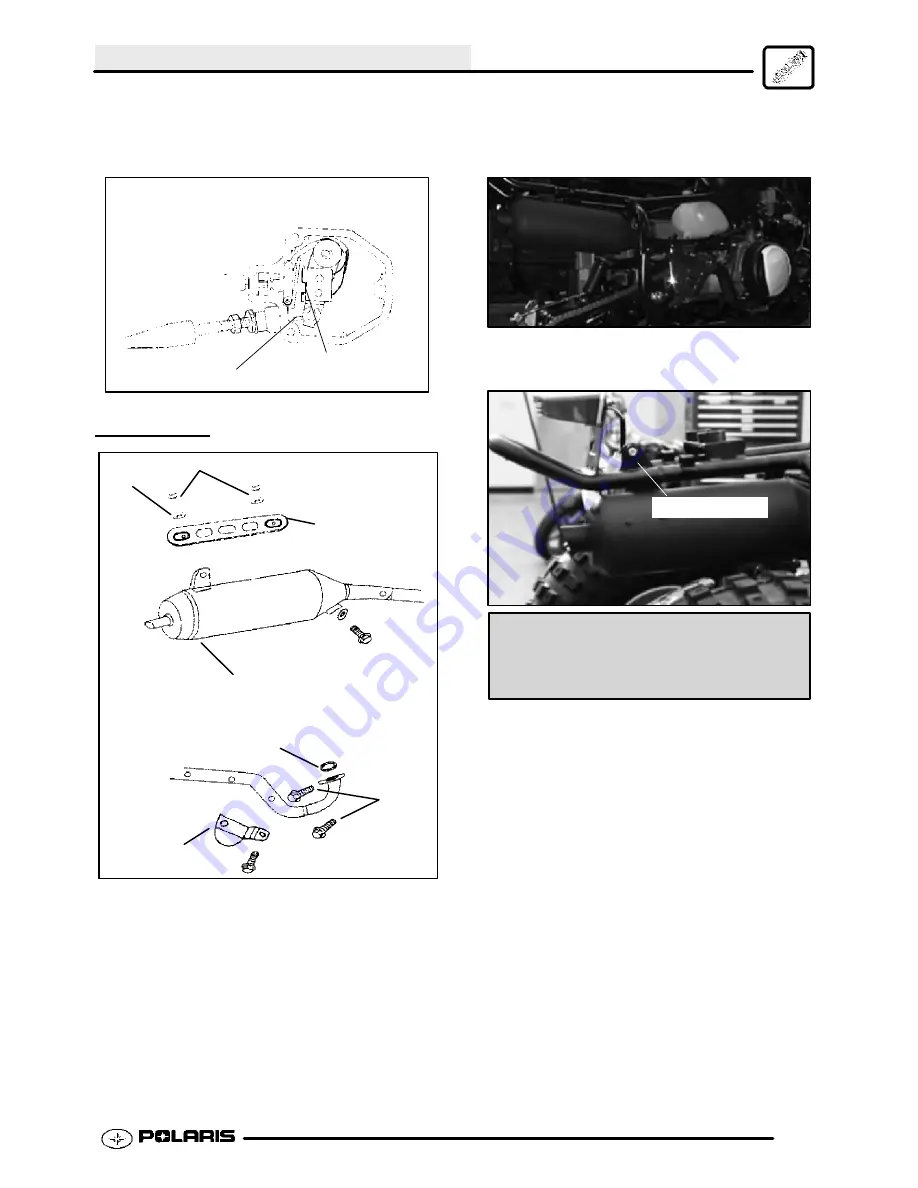
MUFFLER

Bolts

Gaskets

Exhaust Pipe

Protector

Exhaust Pipe

Gasket

Hex Bolts

Fixed Plate

1.

Connect the muffler to the cylinder and install.
Inspect

sealing

gaskets

upon

installation.

Replace if necessary.

2.

Connect the muffler to the mounting bracket on
the frame. Tighten bolt to specification.

Muffler Bracket

Muffler Mounting Bolt Torque:

25 ft.lbs. (34 Nm)

Enfocus Software - Customer Support

Summary of Contents for Sportsman 90

Page 1: ...SCRAMBLER 50 SCRAMBLER 90 SPORTSMAN 90 PREDATOR 90 SERVICE MANUAL PN 9918068 The Way Out ...

Page 2: ...erations component identification and unit repair along with service specifications for the 2003 Polaris Scrambler 50 Predator 90 Scrambler 90 and Sportsman 90 Comments or suggestions about this manual may be directed to Service Publications Dept Polaris Sales Inc 2100 Hwy 55 Medina Minnesota 55340 2003 Sportsman Youth ATV Service Manual PN 9918068 ECopyright 2002 Polaris Sales Inc All information...

Page 3: ...son inspecting or servicing the ATV CAUTION A CAUTION indicates special precautions that must be taken to avoid personal injury or ATV or property damage NOTE A NOTE provides key information to clarify instructions Trademarks Polaris acknowledges the following products mentioned in this manual FLEXLOC Registered Trademark of SPS Technologies Loctite Registered Trademark of the Loctite Corporation ...

Page 4: ...Table of Contents PN 9918068 Chapter 1 General Information Maintenance Chapter 2 Engine Transmission CVT Chapter 3 Carburetion Chapter 4 Body Steering suspension Chapter 5 Electrical ...

Page 5: ...asure Conversion Table 1 7 Tap Drill Charts 1 8 Decimal Equivalent Chart 1 8 Glossary of Terms 1 9 2003 Models E S L S 1 10 Vehicle Inspection Adjustments 1 11 1 13 Transmission Lubrication 1 13 1 14 Throttle Operation Air Screw Adjustment 1 14 Idle Speed Adjustment 1 14 Throttle Cable ETC Adjustments 1 15 1 16 Oil Pump Adjustment Bleeding 1 16 Oil Pump Troubleshooting 1 17 Fuel System 1 17 1 18 C...

Page 6: ... 0 0 Vehicle Descriptor Vehicle Identifier Powertrain Engine Emissions Model Year Plant No Individual Serial No Body Style Check Digit World Mfg ID This could be either a number or a letter SERIAL NUMBER LOCATIONS Whenever corresponding about an engine be sure to refer to the engine serial number This information can be found stamped on the transmission section located by the transmission oil fill...

Page 7: ...GENERAL INFORMATION 1 3 2003 YOUTH MODEL ATVS SCRAMBLER 50 SCRAMBLER 90 SPORTSMAN 90 PREDATOR 90 NOTE Colors will vary upon model ...

Page 8: ...GENERAL INFORMATION 1 4 ...

Page 9: ...matic C V T Sys tem FRONT SUSPENSION A arm with 4 25 10 8 cm Travel A arm with 4 25 10 8 cm Travel A arm with 4 25 10 8 cm Travel A arm with 4 25 10 8 cm Travel REAR SUSPENSION Single Shock Swing Arm with 4 25 10 8 cm Travel Single Shock Swing Arm with 4 25 10 8 cm Travel Single Shock Swing Arm with 4 25 10 8 cm Travel Single Shock Swing Arm with 4 25 10 8 cm Travel FRONT BRAKE Drum Drum Drum Drum...

Page 10: ... POLARIS NUMBER Scrambler 50 Springs Yellow N A P 216 Sportsman 90 Springs Medium Gloss Black 9440 P 067 Scrambler 90 Springs Yellow N A P 216 Predator 90 Springs Indy Red N A P 293 Frame All Medium Gloss Black 9440 P 067 Order direct from Midwest Industrial Coatings 952 242 2000 INSPECTION SCHEDULE Service Item Initial Service After two weeks Monthly Every 6 Months Yearly Air Cleaner C Fuel Filte...

Page 11: ...ck Spring Compressor Tool 2870623 Battery Charger PV 37453 NOTE Special tools can be ordered by Polaris Dealers only through SPX Corporation at 800 328 6657 POLARIS LUBRICANT AND MAINTENANCE PRODUCTS Part No Description Engine Lubricant 2870791 Fogging Oil 2871098 Premium 2 Cycle Engine Oil Quart 2871097 Premium 2 Cycle Engine Oil Gallon 2871240 Premium 2 Cycle Engine Oil 2 5 Gallon 2871566 Premiu...

Page 12: ...ters cc x 0 061 Cubic inches cu in Imperial pints Imp pt x 0 568 Liters l Liters l x 1 76 Imperial pints Imp pt Imperial quarts Imp qt x 1 137 Liters l Liters l x 0 88 Imperial quarts Imp qt Imperial quarts Imp qt x 1 201 US quarts US qt US quarts US qt x 0 833 Imperial quarts Imp qt US quarts US qt x 0 946 Liters l Liters l x 1 057 US quarts US qt US gallons US gal x 3 785 Liters l Liters l x 0 2...

Page 13: ...6 11 32 R 3 8 13 32 13 32 0 0995 0 0937 0 1285 0 125 0 166 0 161 0 196 0 234 0 277 0 265 0 3125 0 3125 0 3437 0 339 0 375 0 406 0 406 3 32 3 32 1 8 1 8 11 64 5 32 13 64 15 64 9 32 17 64 5 16 5 16 11 32 11 32 3 8 13 32 13 32 DECIMAL EQUIVALENTS 1 64 0156 1 32 0312 1 mm 0394 3 64 0469 1 16 0625 5 64 0781 2 mm 0787 3 32 0938 7 64 1094 3 mm 1181 1 8 1250 9 64 1406 5 32 1563 4 mm 1575 11 64 1719 3 16 1...

Page 14: ...t the end of a lever one meter in length applied in a rotational direction l or ltr Liter Left Side Always referred to based on normal operating position of the driver m Meter meters Mag Magneto Magnetic Induction As a conductor coil is moved through a magnetic field a voltage will be generated in the windings Mechanical energy is converted to electrical energy in the stator mi Mile miles mm Milli...

Page 15: ... speed of the ATV Speed can be adjusted by removing or installing the jumper on the CDI A With the jumper installed 50cc models will travel no faster than 10 mph and 90cc models will travel no faster than 15 mph With the jumper removed 50cc models will travel no faster than 15 mph and 90cc models will travel no faster than 30 mph Jumper Removal and Installation 1 Remove the CDI and its rubber moun...

Page 16: ...20 mm Front Brake Lever Travel 50 cc 1 1 8I 28 mm 90 cc 1 3 4 45 mm REAR BRAKE 3 The rear brake is operated using the left hand brake lever To adjust the rear brake setting turn the rear brake adjuster nut until brake is set to specification Rear Brake Lever Free Play 40 80I 10 20 mm Rear Brake Lever Travel 50 cc 1 1 8I 28 mm 90 cc 2 1 2 65 mm VEHICLE INSPECTION CHAIN ADJUSTMENT 1 Remove the rear ...

Page 17: ... 1 Lubricate grease fittings on spindles monthly with Polaris All Season Grease or more frequently if used often Polaris Premium All Season Grease 14 oz PN 2871423 Grease Gun Kit PN 2871312 FRONT SHOCKS AND SPRINGS 1 Inspect the front shocks and springs to ensure proper function If the shock is leaking oil replace The spring preload can be adjusted on the Sportsman 90 by turning the adjuster nut I...

Page 18: ...ricant Polaris Premium Synthetic Gearcase Lubricant PN 2871477 Gallon PN 2871478 12 oz Capacity 10 fl oz 300 ml Capacity at Change 7 oz 200ml Operating Range Oil level visible in sight glass safe zone Drain Plug Torque 14 ft lbs 19 4 Nm TRANSMISSION SPECIFICATIONS To check the level The gearcase fill plug A is located on the top of the gearcase The sight glass B is on the right hand side of the ge...

Page 19: ...tion 3 Replace the throttle cable if worn kinked or damaged AIR SCREW ADJUSTMENT 1 Turn carburetor air screw in clockwise until lightly seated Back screw out the specified number of turns Air Screw Air Screw Adjustment 50 cc 1 2 Turn Out from Lightly Seated 90 cc 1 Turn Out from Lightly Seated 2 Warm up the engine to operating temperature about 10 minutes 3 Set idle speed to 800 RPM NOTE Adjusting...

Page 20: ...r and jam nut Boot Lock nut Ill 1 2 Set parking brake 3 Start engine and set idle to specified RPM NOTE Be sure the engine is at operating temperature See Idle Speed Adjustment 4 Loosen lock nut on in line cable adjuster Ill 1 5 Turn cable adjuster out until engine RPM begins to increase 6 Turn cable adjuster back in until throttle lever has 1 16 16 cm of travel before engine RPM increases 7 Tight...

Page 21: ... purged out of the system Bleed Screw Direction of Pump Rotation OIL PUMP ADJUSTMENT PROCEDURE 1 Before adjusting the oil pump check engine idle RPM and set to specification Adjust if necessary Check engine idle RPM and set to specification before adjustments 2 Check and adjust throttle lever free play ETC switch 3 Apply parking brake 4 Remove fan shroud 5 Start the engine and let it idle 6 Keep a...

Page 22: ...r thermal expansion If you get gasoline in your eyes or swallow gasoline see your doctor immediately If you spill gasoline on your skin or clothing immediately wash it off with soap and water and change clothing Never start the engine or let it run in an enclosed area Gasoline powered engine exhaust fumes are poisonous causing loss of consciousness and death in a short time Never drain the float b...

Page 23: ...il tank Use Premium 2 Cycle Engine Oil when filling the tank CARBURETOR DRAINING The carburetor float bowl should be drained periodically to remove moisture or sediment from the bowl or before extended periods of storage Drain Screw NOTE Drain plug is located on the side of the float bowl 1 Turn fuel valve to the off position 2 Place a container beneath the bowl drain spigot or bowl drain hose 3 L...

Page 24: ...y wash the element in soapy water and dry it Replace filter if necessary 4 Lightly grease the sealing surfaces of the air filter cover Install cover 5 Install three 3 screws and boot clamp WHEELS Inspect all wheels for runout or damage Check wheel bolts and ensure they are tight Do not over tighten the wheel bolts WHEEL HUB AND SPINDLE TORQUE TABLE Item Specification Front Wheel Bolts 22 29 Ft Lbs...

Page 25: ...ection PSI Cold Front Rear 2 Scrambler 50 2 Scrambler 50 3 Scrambler 90 3 Scrambler 90 3 Sportsman 90 3 Sportsman 90 3 Predator 90 3 Predator 90 WARNING Operating an ATV with worn tires will increase the possibility of the vehicle skidding easily with possible loss of control Worn tires can cause an accident Always replace tires when the tread depth measures 1 8 3 cm or less TIRE INSPECTION CAUTIO...

Page 26: ...ed steering components Steering should move freely through entire range of travel without binding Check routing of all cables hoses and wiring to be sure the steering mechanism is not restricted or limited NOTE Whenever steering components are replaced check front end alignment Use only genuine Polaris parts WHEEL ALIGNMENT METHOD 1 STRAIGHTEDGE OR STRING Be sure to keep handlebars centered See no...

Page 27: ...oe tolerance is 1 8 to 1 4 3 to 6 cm toe out This means the measurement at the front of the tire A is 1 8 to 1 4 3 to 6 cm wider than the measurement at the rear B Chalk Line Measurement A Measurement B Ill 1 TOE ALIGNMENT ADJUSTMENT 1 If toe alignment is incorrect measure the distance between vehicle center and each wheel This will tell you which tie rod needs adjusting NOTE Be sure handlebars ar...

Page 28: ......

Page 29: ...isassembly 2 4 2 9 Transmission Service 2 10 2 11 Engine Component Inspection 2 11 2 12 Cylinder Honing 2 12 2 14 Crankshaft Runout Inspection 2 14 Constant Variable Transmission CVT Service 2 16 2 18 Engine Reassembly 2 18 2 22 Kick Start and Spring Installation 2 23 2 24 Starter Drive One Way Clutch 2 24 2 25 Engine Troubleshooting 2 25 2 26 ...

Page 30: ...10 Nm Intake Manifold Bolts 108 in lbs 12 Nm Cylinder Head Nuts 14 ft lbs 19 Nm Drive Clutch Nut 29 ft lbs 39 Nm Driven Clutch Nut Torque 25 ft lbs 34 Nm Transmission Cover Bolts 84 in lbs 9 5 Nm Flywheel 25 ft lbs 34 Nm Oil Drain Bolt Transmission 14 ft lbs 19 Nm Oil Pump Bolts 43 in lbs 5 Nm Fan Housing 84 in lbs 9 5 Nm Fan Bolts 84 in lbs 9 5 Nm Stator Plate 84 in lbs 9 5 Nm Starter Motor Bolts...

Page 31: ...per body panels The Sportsman requires all of the body panels to be removed The Scrambler requires the footrest and the muffler guard to be removed Muffler Guard 2 Remove the air box and carburetor from the chassis Air Box and Carburetor 3 Loosen and remove the drive chain from the drive sprocket Loosen the exhaust mounting bolts from under the engine Remove any other muffler mountings from the en...

Page 32: ...de inspection checklist Exhaust 1 Replace exhaust gaskets Seal connections with high temp silicone sealant 2 Check to be sure all springs are in good condition Engine Break In Period Engine Break In Period is defined as the first 10 hours of engine operation or 2 full tanks of fuel 1 Use only Polaris Premium 2 cycle engine oil Never substitute or mix oil brands Serious engine damage can result 2 U...

Page 33: ...ng washer and the one way clutch from the crankshaft 6 Remove the primary fixed sheave and washerclaw 7 Remove the bushing the primary sliding sheave and the cam plate assembly Primary Sheave NOTE When removing the primary sliding sheave and the cam plate assembly use two hands to hold the cam plate and the primary sliding sheave together This prevents the roller weights from falling out of the as...

Page 34: ...ing as needed O Ring 11 Remove the three phillips screws holding the fan in place Remove the fan 12 Remove the spring washer and nut from the shaft 13 Remove the flywheel using flywheel puller Flywheel Puller Flywheel Puller PA 45153 14 Scribe an alignment mark on the stator backing plate and the crankcase for proper alignment upon engine assembly Remove stator assembly ...

Page 35: ...ive gear Oil Pump Drive Gear Removal Tool PN 0450699 17 Remove the oil seal bracket NOTE To ease disassembly clean the grease out of the oil pump chamber area and note the amount That same amount of grease is reinserted into the chamber later in the engine assembly 18 Remove the dowel pin from the crankshaft 19 Remove the external circlip from the crankshaft 20 Remove the circlip to disassemble th...

Page 36: ...ylinder and gaskets 23 Make note of the orientation of the piston There is an arrow on the piston head pointing toward the exhaust side OIl Pump Arrow 24 Remove the piston pin clip and the piston pin 25 Remove the needle bearing from the piston pin bore 26 Carefully remove the piston rings so no damage is done to the ring lands Discard the rings and replace them with new rings ...

Page 37: ...e separating tool to disassemble the right and left crankcase halves Crankcase Separating Tool PN 0450700 30 Use the crankshaft removal tool to remove the crankshaft Crankshaft Removal Tool PN 0450697 31 Remove the external snap ring on the output shaft bearing and remove the oil seal Replace the seals or bearing as needed 32 Remove the external snap ring to remove the crankshaft bearing ...

Page 38: ...rimary Drive Assy Primary Drive Axle Assy Main Axle 3 Remove the washer and the driven clutch gear 4 Remove the drive axle assembly Inspect for signs of wear 5 Remove the bolt and washer to aid removal of the bearing and the primary drive assembly Transmission Cover Primary Drive Assy Bearing Bolt Washer DRIVE SPROCKET CIRCLIP BEARING OIL SEAL CIRCLIP BEARING DRIVE AXLE ASSY BEARING MAIN AXLE WASH...

Page 39: ...s as shown in illustration at left Normal gap should be 002 0 05 mm or less If gap is excessive resurfacing head or replacement is needed Cylinder Head Warp Service Limit 002I 0 05 mm Cylinder Inspection 1 Inspect the surface of the cylinder for warpage Clean all gasket residue completely from sealing surface Use a feeler gauge and straight edge Measure the gap six 6 different ways as shown in ill...

Page 40: ...n piston ring 1 2 1 3 cm from the top of the cylinder using the piston to push it squarely into place Measure installed gap with a feeler gauge at both the top and bottom of the cylinder Replace rings if the installed end gap exceeds the service limit Piston Ring Installed Gap Service Limit 030I 0 75 mm Piston Pin Hole Inspection 1 Using a telescoping gauge or similar bore gauge measure the inside...

Page 41: ...each stroke G Release the hone at regular intervals and inspect the bore to determine if it has been cleared and to check piston fit NOTE Do not allow cylinder to heat up during honing The thinner areas of the liner around the ports will expand causing uneven bore G After honing has been completed inspect all port opening areas for rough or sharp edges Apply a slight chamfer to all ports to remove...

Page 42: ...ck each fiber reed for stress marks or missing material Reed Pedal Clearance 015 38 mm max Exaggerated for illustration Reed Valve Air Gap Service Limit 015I 0 4 mm CRANKSHAFT RUNOUT Lubricate the bearings and clamp the crankshaft securely in the holding fixture Refer to the illustrations Crankshaft Alignment Fixture PN 2870710 1 If the runout of the crankshaft is more than 004 100mm on the MAG si...

Page 43: ...for scoring grooving or abnormal wear Primary Sheave NOTE When removing the primary sliding sheave and the cam plate assembly use two hands to hold the cam plate and the primary sliding sheave together This prevents the roller weights from falling out of the assembly 5 Remove the roller weights from the primary sliding sheave Check the rollers for wear and scoring Weight Rollers 6 Remove the drive...

Page 44: ...r caliper to check the length of the compression spring At full extension the measurement should be no less than 2 74 69 7 mm If out of specification replace the spring Driven Compression Spring Service Limit 2 74I 69 7 mm CVT Belt Inspection 1 Inspect the surface of the drive belt for uneven wear or grease deposits Using a vernier caliper measure the width of the belt The service limit of the bel...

Page 45: ...Install the primary fixed sheave and washer claw 5 Install the nylon lock nut the cone spring washer and the one way clutch onto the crankshaft Torque the drive clutch nut to specification Drive Clutch Nut Torque 29 ft lbs 39 Nm 6 Install the inside washer the idle gear and the outside washer onto the pin shaft 7 Install the idle gear plate Torque the bolts to specification Idle Gear Bolt Torque 8...

Page 46: ...Install the crankshaft in one of the crankcase halves Install a new crankcase gasket and install the other side of the crankcase Torque the crankcase bolts to the specification and pattern 1 2 3 4 5 6 Torque pattern Crankcase Bolt Torque 86 in lbs 10 Nm Oil Pump Installation 3 Install the dowel pin into the crankshaft 4 Install the oil seal bracket 5 Carefully install the oil pump drive gear on th...

Page 47: ...grease Oil Pump Bolt Torque 43 in lbs 5 Nm 8 Refill the oil pump gear chamber with the same amount of grease that was removed from the chamber during disassembly Polaris All Season Grease 14 oz PN 2871423 Stator Installation 9 Install a new stator gasket 10 Install the stator Use the alignment marks previously made during the disassembly of the stator Torque the bolts to specification Stator Mount...

Page 48: ...ll the new piston rings so no damage is done to the piston or ring lands Piston Installation 14 Install the needle bearing into the piston pin bore 15 Install the piston pin and the piston pin clip NOTE The piston pin clip gap should faceup ordown 3 o clock or 9 o clock position see illustration Properly lubricate the rings and connecting parts before installation NOTE Make sure the arrow on the t...

Page 49: ...l Installation 18 Install the washer and needle bearing Carefully install the starter wheel onto the crankshaft Washer Needle Bearing 19 Install the fan Torque the fan bolts to specification Fan Bolt Torque 84 in lbs 9 5 Nm 20 Install a new crankcase cover gasket grommets and crankcase breather tube Install the air filter and the crankcase cover Torque the crankcase bolts to specifications Crankca...

Page 50: ...sis Secure the engine with the engine mounting bolts Engine Mounting Bolts 24 Connect the oil cable to the oil pump Tighten the cable 25 Install the fan cover 26 Connect the exhaust pipe to the engine and frame mounting areas 27 Install the air box and carburetor Air Box and Carburetor 28 Install the body panels ...

Page 51: ...A positioned on post Note the spring tab B The tab must be pre wound approximately 5 8 turn about 225 degrees to point C in order to install the kick shaft gear assembly A B C 3 Grease and install the bushing in the kick shaft boss 4 Install the kick shaft as shown with the edge of the gear resting on the spring hook post A Grasp the spring firmly with duckbill or needle nosepliers between the inn...

Page 52: ...le gear plate two washers and idle gear from the pin shaft NOTE There is one washer on the inside of the idle gear and one washer on the outside of the idle gear 3 Remove the washer and needle bearing Carefully remove the starter wheel from the crankshaft Washer Needle Bearing 4 To disassemble the one way assembly remove the three phillips screws from the starter wheel Inspect components for signs...

Page 53: ...ch G ETC switch mis adjusted G Restricted air filter main or pre cleaner or breather system G Improperly assembled air intake system G Restricted air breather system G Oil contaminated Engine Turns Over But Fails to Start G No fuel G Dirt in fuel line or filter G Fuel will not pass through fuel valve G Tank vent plugged or pinched G Carb starter circuit plugged G Engine flooded G Low compression h...

Page 54: ...g broken or sticking G Reeds broken or bent Backfiring G ETC or speed limiter system malfunction G Fouled spark plug or incorrect plug or plug gap G Carburetion faulty lean condition G Exhaust system air leaks G Ignition system faulty Spark plug cap cracked broken Ignition coil faulty Ignition or kill switch circuit faulty Ignition timing incorrect Sheared flywheel key G Poor connections in igniti...

Page 55: ...lot Air Screw Air Fuel Mixture 3 5 3 6 Jet Needle Needle Jet Throttle Opening 3 6 3 7 Throttle Valve Main Jet 3 7 Pilot System 3 8 Slide Cutaway 1 8 3 8 Throttle 3 8 Jet Needle Needle Jet 3 8 3 4 Throttle 3 9 Main Jet 3 4 to Full Throttle 3 9 Fuel Delivery 3 9 3 10 Vent System Float Height 3 10 Needle and Seat Leakage Test 3 10 Carburetor Float Bowl Draining 3 11 Cold Weather Starting Procedure 3 ...

Page 56: ...97 1 Nozzle Main 90cc 0450096 1 Nozzle Main 50cc 10 0450976 1 Float Carb 11 0450118 1 Pin Float 12 0450086 6 Bolt Pan Phillips 13 0450099 1 Tube Overflow 14 0450105 1 Plug Drain 15 0450108 1 Bolt Pan Phillips 16 0450895 1 Valve Set Needle 17 0450095 1 Seal Float Chamber 18 0451022 1 Asm Carburetor Incl 1 30 19 0450923 1 Nozzle Choke 20 0451026 1 Valve Choke 21 0451029 1 Spring Choke Return 22 0451...

Page 57: ...ir is less dense with reduced oxygen Polaris Youth Carburetors are calibrated for an altitude of 0 6000 ft 0 1800 meters and ambient temperatures between 40 and 80 F 5 to 26 C Carburetors must be re calibrated if operated outside this temperature and or altitude range The jetting installed in production is not intended for all altitudes and or temperatures In addition air screw pilot screw adjustm...

Page 58: ...es are required for high altitude operation CARBURETOR JETTING IMPORTANT The following guidelines must be followed when establishing a main jet setting 1 Select the lowest anticipated temperature at which the machine will be operated 2 Determine the lowest approximate altitude at which the machine will be operated 3 Select the correct main jet from the chart in the specifications section CAUTION A...

Page 59: ...flowing from the fuel pump into the float chamber through the needle valve reaches the constant fuel level the floats rise When the buoyancy of the float and the fuel pressure of the fuel pump balance the needle valve seals the orifice in the needle seat preventing further fuel delivery and the level of fuel in the bowl remains relatively constant The fuel level in the bowl assists in controlling ...

Page 60: ...ip inserted into one of the five slots provided in the head of the jet needle The previous chart shows the variation of fuel flow based on the height of the E clip JET NEEDLE The jet needle has five adjustment grooves cut into the upper portion and is tapered from approximately the middle of the needle to the lower end The top is fixed to the center of the throttle valve by the needle clip and the...

Page 61: ...cutaway By controlling air flow the negative pressure over the needle jet is regulated in turn varying the fuel flow Cutaway Air Box Side Engine Side Higher cutaway number leaner mixture Throttle Valve The throttle valves are numbered 1 0 1 5 2 0 etc according to the size of the cutaway The higher the number the leaner the gasoline air mixture MAIN JET When the throttle opening becomes greater and...

Page 62: ... engine to maintain a 14 1 air fuel ratio at part throttle A steep angle would indicate a fairly lean mixture because there is less resistance to air flow A flat angle would provide a much richer mixture because there is more resistance to air flow The venturi shape can be adjusted for each engine s breathing characteristics by using a different valve cutaway angle A number will be stamped into th...

Page 63: ...er out of the needle jet allowing greater fuel flow Under full throttle opening the cross sectioned area of clearance between the jet needle and the needle jet becomes greater than the cross sectioned area of the main jet Thus the main jet is now controlling the amount of fuel flow Air Jet Throttle Valve Jet Needle By pass Pilot Outlet Pilot Jet Needle Jet Main Jet Air Box Side Engine Side General...

Page 64: ...ine damage All vent lines must be properly routed to prevent damage to the line and to prevent contaminants from entering the fuel system FLOAT HEIGHT 1 Invert the carburetor and remove float bowl 2 Rest the float tongue lightly on the inlet needle valve pin without compressing the spring 3 The float should be parallel 1 mm to the gasket surface on all youth model ATV carburetors When setting the ...

Page 65: ...is located on the side of the float bowl 1 Turn fuel valve to the off position 2 Place a clean container beneath the bowl drain spigot or bowl drain hose 3 Loosen drain plug and allow fuel in the float bowl and fuel line to drain completely 4 Inspect the drained fuel for water or sediment 5 TIghten drain plug 6 Turn fuel valve to ON OFF RES ON 7 Inspect carburetor for fuel leaks 8 Start machine an...

Page 66: ... again for 5 seconds 4 If the battery is not charged enough to rotate the engine effectively place a battery charger on the battery or use the kick start lever 5 If engine will not start check spark plug for fouling DEALER SET UP FUEL SYSTEM RECOMMENDATIONS 1 Loosen carburetor drain plug screw and drain old fuel photo1 2 Remove fuel line at carburetor and pressurize the fuel tank or vacuum the fue...

Page 67: ...s up backfire G Air intake restricted inspect intake duct G Air filter dirty plugged G Electric choke inoperative G Incorrect pilot air fuel screw adjustment G Faulty inlet needle and seat G Faulty inlet needle seat O Ring G Float level too high G Poor fuel quality old fuel G Loose jets G Worn jet needle needle jet or other carburetor parts G Dirty carburetor air bleed passages or jets G Fouled sp...

Page 68: ...FUEL SYSTEM CARBURETION 3 14 NOTES ...

Page 69: ... Exploded View 4 3 Engine Mounting 4 3 Shocks and Springs 4 4 Suspension A Arms 4 4 Steering 4 5 Front Brake 4 6 4 7 Rear Brake and Axle 4 7 4 9 Fuel and Oil Tank 4 9 Scrambler Front and Rear Cab 4 10 Sportsman Front and Rear Cab 4 10 4 11 Sportsman Handlebar Assembly 4 11 4 13 Scrambler Handlebar Assembly 4 13 4 15 Muffler Assembly 4 15 ...

Page 70: ...BODY STEERING SUSPENSION 4 2 FRAME Side View Front View Rear View ENGINE MOUNTING Rubber Bushings Mount Tube Engine Bracket Rubber Bushing ...

Page 71: ...g Bolts 43 ft lbs 60 Nm Rear Cover Mounting Bolts 84 in lbs 10 Nm Fuel Tank Mounting Bolts 103 in lbs 12 Nm Oil Tank Mounting Bolts 103 In lbs 12 Nm Front Bumper Mounting Bolts 103 in lbs 12 Nm Cab Mounting Bolts 103 in lbs 12 Nm Muffler Mounting Bolts 25 ft lbs 34 Nm NOTE Refer to exploded views throughout this chapter for identification and location of components SPECIAL TOOLS Description Part N...

Page 72: ... The rear spring can be adjusted for more or less spring preload depending on rider preference SUSPENSION A ARMS Right A arm Bushings Upper Spindle Bushing Lower Spindle Bushing Left A arm Right Spindle Left Spindle Grease Fitting Cap 1 Mount the A arms to the frame body The A arm marked R is for right side and A arm marked L is for left side Torque the bolts to specification Mount the shock in th...

Page 73: ...Seal Spacer Washer Nut 1 Grease the steering post sleeve and insert in place Mount the steering post clamps on post Install the steering post and tighten the steering post mount nuts to specification Steering post mounts Steering Post Mount Nut Torque 103 in lbs 11 6 Nm 2 Install oil seals bearing steering nut and associated hardware on the bottom of the steering post Torque nut to specification S...

Page 74: ... 33 40 ft lbs 45 55 Nm Outer Tie Rod Bolt Torque 33 40 ft lbs 45 55 Nm Tie Rod Jam Nut Torque 12 14 ft lbs 17 19 Nm FRONT BRAKE Right Brake Plate Right Brake Arm Brake Shoes Retainer Spring Return Spring Brake Cable 1 Front brake backing plate assembly components Brake Arm Brake Cam Shaft Return Spring Brake Plate 2 Front brake shoe and brake drum There are oil seals and bearings in the front brak...

Page 75: ...Plates Rear Cover 1 Apply grease to the swing arm spacer tube The swing arm assembly must be mounted first NOTE The swing arm assembly includes chain protector 2 Install the swing arm to the frame and tighten the mounting bolt to specification Install rear shock and spring Tighten shock mounting bolts to specification Swing Arm Mounting Bolt Torque 26 30 ft lbs 36 40 Nm Rear Shock Mounting Bolt To...

Page 76: ...ot tighten to specified torque at this time 6 Install the drive sprocket on the rear wheel axle 7 Install the right and left spacer tube on the rear wheel axle Spacer Tube 8 Install the wheel hub and tighten axle nut to specification Axle Nut Torque 78 81 ft lbs 108 112 Nm 9 Install rear brake cable on brake arm 10 Install chain on drive sprocket and tighten sprocket bolts to specification Sprocke...

Page 77: ...the rear cover Torque bolts to specification Rear Cover Rear Cover Bolt Torque 84 in lbs 10Nm FUEL AND OIL TANK 1 Install fuel tank in the frame and tighten bolts to specification Make sure the fuel tank pads are in place and in good condition and the vent line is unobstructed Fuel Tank Mounting Bolt Torque 103 in lbs 12 Nm 2 Install the oil tank to the frame and tighten bolts to specification Alw...

Page 78: ...nd rear cab to the frame The front cab is mounted on positions 1 and 2 The rear cab is mounted on position 3 1 2 3 3 Install the front and rear cab to the frame and tighten the mounting bolts to specification Front Cab Assy Rear Cab Assy Cab Mounting Bolt Torque 103 in lbs 12 Nm 4 The front cab mounts to the front bracket of the frame SPORTSMAN FRONT AND REAR CAB INSTALLATION 1 Install the bumper ...

Page 79: ...Cab Mounting Bolt Torque 103 in lbs 12 Nm 4 The front cab mounts to the front bracket of the frame SPORTSMAN HANDLEBAR ASSEMBLY UPPER POD ASSEMBLY LOWER POD ASSEMBLY HANDLEBAR PROTECTIVE PLATE CLAMPS WASHER NUT BOLTS Brake Lever Right Hand Control Handlebar Grip 1 Install the lower pod assembly 2 The handlebar assembly includes the right and left side brake levers the throttle control and the left...

Page 80: ...ghten the clamp bolts to specification Handlebar Mounting Clamp Bolt Torque 84 in lbs 10 Nm 6 Check freeplay of the right side and left side front brake cables as shown Adjust to specification Front Brake Lever Free Play 40 80I 10 20 mm Front Brake Lever Travel 50 cc 1 1 8I 28 mm 90 cc 1 3 4 45 mm 7 Check freeplay of the rear brake cable Adjust to specification Rear Brake Lever Free Play 40 80I 10...

Page 81: ...on Pod Mounting Screw Torque 42 in lbs 4 7 Nm SCRAMBLER HANDLEBAR ASSEMBLY ROUND NUTS PROTECTIVE PADDING HANDLEBAR HANDLEBAR COVER CLAMPS WASHER NUT BOLTS Brake Lever Right Hand Control Handlebar Grip SPACERS 1 Install the lower clamps 2 The handlebar assembly includes the right and left side brake levers the throttle control and the left side control switch Install these items loosely on the hand...

Page 82: ...n the steering post and tighten the clamp bolts to specification Handlebar Mounting Clamp Bolt Torque 84 in lbs 10 Nm 6 Check freeplay of the right side and left side front brake cables as shown Adjust to specifications Front Brake Lever Free Play 40 80I 10 20 mm Front Brake Lever Travel 50 cc 1 1 8I 28 mm 90 cc 1 3 4 45 mm 7 Install the rear brake cable Adjust to specifications Rear Brake Lever F...

Page 83: ...Button A Cast Aluminum Throttle Housing MUFFLER Bolts Gaskets Exhaust Pipe Protector Exhaust Pipe Gasket Hex Bolts Fixed Plate 1 Connect the muffler to the cylinder and install Inspect sealing gaskets upon installation Replace if necessary 2 Connect the muffler to the mounting bracket on the frame Tighten bolt to specification Muffler Bracket Muffler Mounting Bolt Torque 25 ft lbs 34 Nm ...

Page 84: ...BODY STEERING SUSPENSION 4 16 NOTES ...

Page 85: ...Current Draw Key Off Test 5 8 Charging System Break Even Test 5 9 Alternator Output Test 5 9 Ignition System Spark Plug 5 10 Starter System Troubleshooting Voltage Drop Test 5 10 Starter System Diagnosis 5 11 Starter Motor Disassembly 5 12 Brush Inspection Replacement 5 12 5 13 Armature Testing 5 13 Starter Assembly 5 13 5 14 Electronic Throttle Control ETC 5 14 Cranking Tests 5 15 Coil and Enrich...

Page 86: ...m timing is non adjustable The specifications on page 1 3 are intended for reference only 2003 MODEL YOUTH ATV SPEED RESTRICTION Per ANSI SVIA 1 2001 sec 6 1 3 the AS DELIVERED TO THE CON SUMER The speed of youth models is restricted to under 10 MPH for the 50 cc models and under 15 MPH for the 90 cc models The dealer CANNOT under any circumstances either prior to the sale or later even at the con...

Page 87: ... place and remove lens cover 2 Remove bulb and replace it with recommended bulb Apply Nyogelt grease PN 2871329 3 Reinstall the lens cover removed in step 1 4 Test the brakelight to see that it s working BATTERY Youth ATV batteries have been upgraded to a maintenance free unit with more reserve capacity A new battery holder was designed to accommodate the battery s larger size For charging it is r...

Page 88: ...ut into regular service within 30 days Polaris Youth ATV batteries are a maintenance free design Do not attempt to add water or electrolyte NOTE New batteries must be fully charged before use or battery life will be significantly reduced 10 30 of the battery s full potential 1 Remove the battery battery acid and accessories from the box Electrolyte Funnel Battery NOTE Wear safety glasses and rubbe...

Page 89: ...CUIT VOLTAGE TEST Battery voltage should be checked with a digital multitester Readings of 12 5 or less require further battery testing and charging See open circuit voltage chart and Load Test NOTE Batteries should be kept at or near a full charge as possible If the battery is stored or used in a partially charged condition crystal sulfation will form on the plates reducing the efficiency and ser...

Page 90: ...r dis charge and require checking more often G Maintenance Free Batteries should read 12 8 13 0v when fully charged G Keep the battery free of dirt and grime G Inspect the cables clamps and fittings for damage or loose con nections G Clean terminals and connectors as needed G Pull battery or disconnect battery cables during storage G If a battery is stored test regularly and charge it if the volta...

Page 91: ...black ground cable last Coat battery bolt threads with corrosion resistant Nyogelt grease Secure battery with the holder strap Nyogelt Grease PN 2871329 WARNING To avoid the possibility of explosion connect positive red cable first and negative black cable last YOUTH ATV BATTERY CHARGING CHART State of Charge Voltage Action Charge Time 100 12 8 13 0v None Full Charge None Required 75 12 5 12 8v Sl...

Page 92: ...lator rectifier connections and ground battery connections cir cuit breaker and connecting wires Repair or replace faulty wiring or components If all of the previous tests indicate a good condition but the charging voltage does not rise above battery voltage at the connector replace the voltage regulator No Yes No Yes Perform system Break Even Amperage test outlined on Page 5 9 Does charging occur...

Page 93: ...k even point may vary slightly The battery should be fully charged before performing this test G Connect an ammeter set to DC amps in series between the negative battery cable and terminal G Connect a tachometer according to manufacturer s instructions G With engine off and the key and kill switch in the ON position the ammeter should read negative amps battery discharge Reverse meter leads if a p...

Page 94: ...otor or starter solenoid see Voltage Drop Tests G Faulty starter button G Faulty ignition switch Do other systems function G Faulty starter solenoid or starter motor G Engine problem seized or binding Can engine be rotated with kick starter Starter Motor Turns Over Slowly G Battery discharged G Excessive circuit resistance poor connections see Voltage Drop Test below G Engine problem seized or bin...

Page 95: ...mponent Reconnect the solenoid Connect the tester black lead to the battery positive and the red lead to the solenoid end of the battery to solenoid wire De press starter button Reading should be less than 1 V D C Clean the battery to solenoid cable ends or replace the cable Connect the black tester lead to solenoid end of battery to solenoid cable Connect red tester lead to solenoid end of soleno...

Page 96: ...tarter Bolts 2 Remove the two bolts and washers 3 Remove housing while holding the armature and brush holder section together BRUSH INSPECTION REPLACEMENT 1 Using a digital multitester measure the resistance between the cable terminal and the insulated brush The reading should be 3 ohms or less Measure the resistance between the cable terminal and brush housing Make sure the brush is not touching ...

Page 97: ... Bars discolored in pairs indicate shorted coils requiring replacement of the starter motor 6 Place armature in a growler Turn growler on and position a hacksaw blade or feeler gauge lengthwise 1 8 3 cm above armature coil laminates Rotate armature 360 If hacksaw blade is drawn to armature on any pole the armature is shorted and must be replaced 7 Inspect permanent magnets in starter housing Make ...

Page 98: ...ble tension In the event of a mechanical problem in the throttle mechanism cable tension is lost the switch contacts open connecting the CDI grey wire from ground limiting engine RPM to 1500 Electronic Throttle Control ETC Switch ETC Micro Switch Button A Cast Aluminum Throttle Housing Ill 1 Electronic Throttle Control Throttle is Open ETC Switch is Closed Connec tion from Grey to Black Throttle i...

Page 99: ...0 3 0 4 Volts AC Black Red to Black Bullet Connector 90 120 Volts AC Peak Reading Cranking Voltage Wire Color From Stator Wire Description A C Peak Output With Peak Reading Adapter and meter set to DCV scale Yellow Red to Black 3 Prong Plug 7 85 Volts DC White to Black 3 Prong Plug 9 50 Volts DC White Red to Black Bullet Connector 4 90 Volts DC Black Red to Black Bullet Connector 203 Volts DC Whit...

Page 100: ...ect G Fouled spark plug G Faulty spark plug cap or poor connection to high tension lead G Related wiring loose disconnected shorted or corroded G Engine Stop switch or ignition switch faulty G ETC switch misadjusted or faulty G Poor ignition coil ground e g coil mount loose or corroded G Faulty stator measure resistance of all ignition related windings G Incorrect wiring inspect color coding in co...

Page 101: ...y Switch Off Engine LH Engine Cut off Switch NOTE Connection closed in RUN position Connection open in OFF position NOTE CDI BLK WHT must have ground to run BLK Y NOTE If the key does not shut off the machine the wire on this circuit may be grounded Scrambler 50 90 Predator 90 Sportsman 90 Quick Reference Wire Diagram BLK ETC Switch is OPEN the engine is limited to 1500 RPM Main Switch OR GRN Y LH...

Page 102: ...ELECTRICAL 5 18 SCRAMBLER 50 WIRING DIAGRAM Scrambler 50 ...

Page 103: ...ELECTRICAL 5 19 SCRAMBLER 90 SPORTSMAN 90 PREDATOR 90 WIRING DIAGRAM Sportsman 90 Scrambler 90 Predator 90 ...

Page 104: ...sting 3 10 Carburetor Operation 3 4 Carburetor Specifications 3 4 Carburetor System Function 3 3 Carburetor Venting Systems 3 10 Chain Adjuster Lock Nut Torque 1 11 Chain Adjustment 1 10 Chain Tension Spec 1 10 Chain Tension Specification 4 9 Chain Tensioner Nut Torque 4 9 Charging System Break Even Test 5 9 Charging System Testing 5 8 Choke Adjustment 1 14 Clutch Brake Lining Service Limit 2 16 C...

Page 105: ...0 Front and Rear Cab Scrambler 4 10 Front and Rear Cab Sportsman 4 10 Front Brake Inspection 1 10 Front Brake System 4 6 Front Bumper Mounting Bolt Torque 4 10 4 11 Front Shock and Spring Inspection 1 11 Fuel and Oil Tank 4 9 Fuel Filter Maintenance 1 16 Fuel Line Maintenance 1 16 Fuel System Warnings 1 16 Fuel Tank Mounting Bolt Torque 4 9 G Glossary of Terms 1 8 Grease Fitting Lubrication 1 11 H...

Page 106: ...1 Rear Shock Mounting Bolt Torque 4 7 Reed Valve Air Gap Service Limit 2 14 Reed Valve Inspection 2 14 S Serial Number Locations 1 2 Shock Mounting Bolt Torque 4 4 Shocks and Springs Exploded View 4 4 Slide Cutaway 3 8 Spark Plug Recommendation 5 10 Special Tools 3 3 Special Tools Electrical 5 2 Special Tools Engine 2 2 Special Tools Suspension 1 5 4 3 Specifications General 1 3 Specifications Tor...

Page 107: ...n Lubrication 1 12 Troubleshooting Engine 2 25 Troubleshooting Fuel System Carb 3 13 Troubleshooting Ignition System 5 16 Troubleshooting Spark Plug 2 25 Troubleshooting Starter System 5 10 V Vechicle Inspection 1 10 Vent Line Maintenance 1 16 Voltage Drop Test 5 10 Voltage Test Open Circuit 5 5 VIN Identification 1 2 W Wheel Hub and Spindle Torque Table 1 18 Wheel Inspection 1 18 Wheel Installati...

Page 108: ......

Page 109: ...PN 9918068 Printed in USA ...

Reviews: