
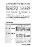
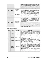
Here are the steps which the installer must follow in order to
flash the Hood Pin switch
:
The Installer …
The Module …
Press and
hold
the Hood Pin switch for 4 seconds.
Release
the Hood Pin switch.
The Parking Lights will turn
ON
.
While the Parking Lights are
ON
,
press down
the Hood
Pin switch once more.
Release
the Hood Pin switch again.
Caution!
If you press down and release the Hood Pin
Switch too many times, you will enter
Diagnostic Mode
rather than Programming Mode.
The Parking Lights will stay
ON
for 20 seconds
You now have 20 sec. to select one of the sub-menus.
Table 1: Flashing the Hood Pin switch
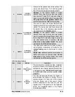
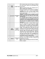
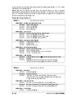
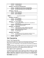
Once the Remote Car Starter has entered Programming Mode, you will have a selection of many
different sub-menus, which will be described later in this Guide:
a. Transmitter
Programming
b. Programming
Options
c.
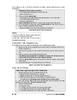
Honk/Horn Timing (if available)
d. Tach
Programming
Remember:
Once the Parking Lights are
ON
(solid), you have up to 20 seconds to select a sub-menu. If you do
not select a sub-menu within 20 seconds, the Remote Car Starter will exit Programming Mode and
you will have to flash the Hood Pin switch once again.
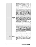
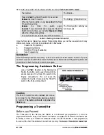
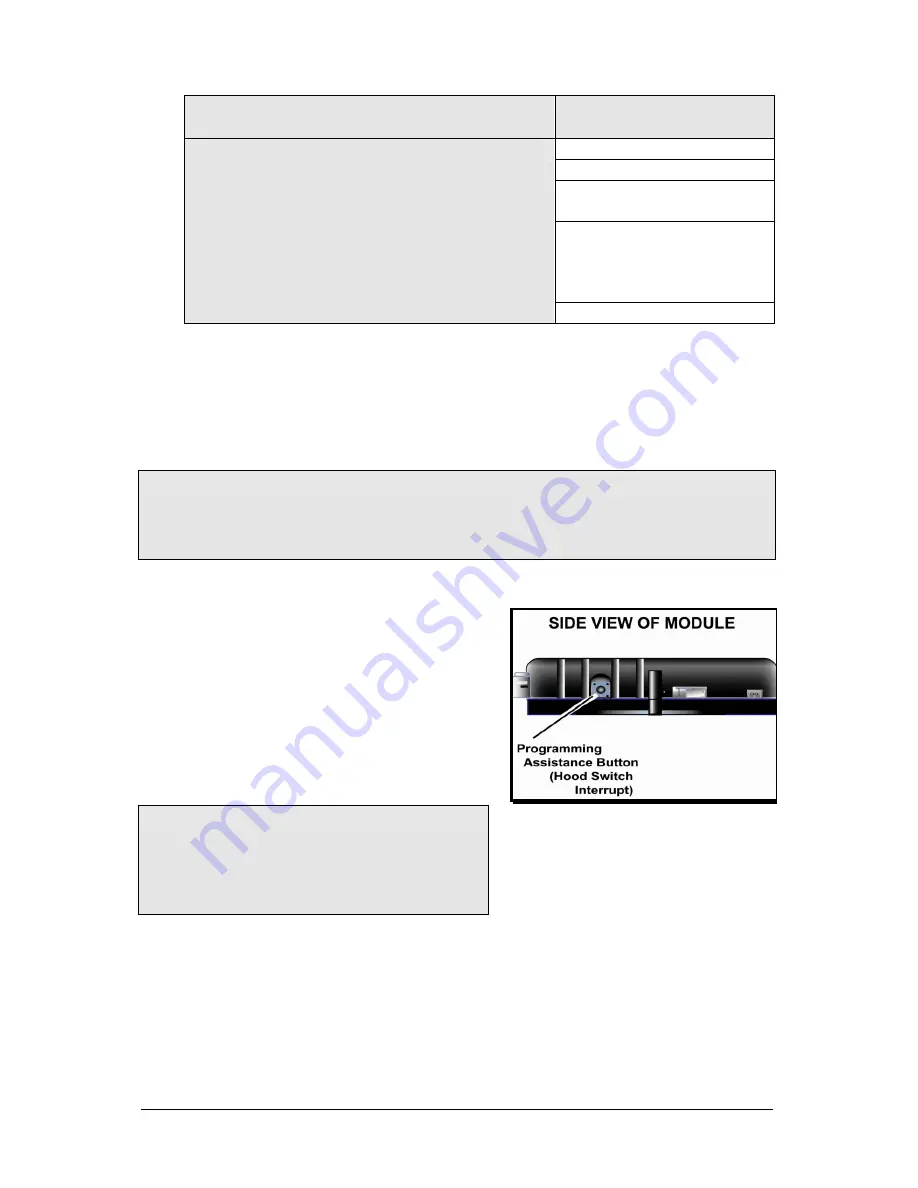
The Programming Assistance Button
(A.k.a. the
PAB
.) Mounted on the Remote Car
Starter, this button can be used from within the
vehicle instead of the Hood Pin switch in the
Engine compartment. This will spare the
installer the trouble of accessing the Hood Pin
switch in the Engine compartment.
Caution
The Hood Pin switch must be installed and connec-
ted in order for the Programming Assistance Button
to function.
The button will work only when the
Hood is up.
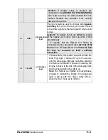
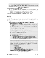
Programming a Transmitter
Before you Proceed
The Transmitter of the Remote Car Starter is not delivered pre-programmed: it must be
programmed after the wiring of the Remote Car Starter is completed. The Remote Car Starter has
the ability to retain up to 4 different Transmitter codes; if a fifth Transmitter is code-programmed,
the code of the first Transmitter will be lost from memory.
To erase all Transmitter codes from
P. 12
Installation
Guide
PS-3185SH


