background image

PS-3185SH 

Installation Guide  

P. 17


d.


To decrease the pulse by 10 ms, press the 

TRUNK

 button. 

5.


To save the new settings: press 

LOCK

 and 

UNLOCK

. If 3 honks are returned the new 

settings have been saved. 

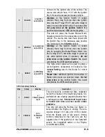
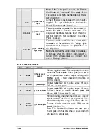
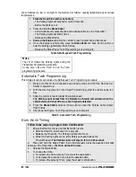
Table 9: Adjusting Honk Duration 

Otherwise close the Hood to cancel the changes. 

For each timing change, the Horn will honk with the new settings, except in the 
following cases: 


When the lower limit of 5 ms is reached, there will be a 1/4-sec. honk. 


When the upper limit of 200 ms is reached, there will be a 3/4-sec. honk. 

A system reset will set the Remote Car Starter back to the default values: 30 ms. 
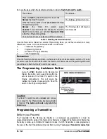
 

Testing 

Before putting back the vehicle together, it is recommended to check that the system operates 
properly. The following testing procedures should be used to verify proper installation and 
operation of the system. Before testing, make sure that all connections are soldered and that the 
unit is plugged in. 

‰


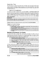
Make sure the Remote Car Starter properly 

enters and exits Ready Mode

Setting the system to Ready Mode 

1.


Ensure that all the Doors are closed and that the Gear Shift Lever is in the 

NEUTRAL


position. 


2.


With the Engine already running, apply the Parking Brake and release the Brake 
Pedal. 

Make sure to release the Brake Pedal. 


3.


Within 20 sec. push 

LOCK

UNLOCK

 or 

START

 on the Transmitter. 

The Parking Lights will flash 3 times quickly and remain lit. 


4.


Remove the key: the Engine will go on running. 


5.


Exit the vehicle and close the Door. 

6.


Press and hold either: 
a.


LOCK

 to lock the Doors and shut down the Engine or enter Turbo Mode ; 

b.


UNLOCK

 to unlock the Doors and shut down the Engine or enter Turbo Mode ; 

c.


STOP

 to shut down the Engine without affecting the Doors. 

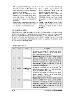
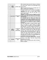
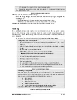
Table 7: entering Ready Mode 

Remaining in ready Mode 

Once the vehicle is in Ready Mode, you can start and stop the vehicle at wish. 
However, should any one of the following occur, the vehicle will exit Ready Mode, thus 
disabling remote start capabilities until Ready Mode is restored: 


Door opened, 


Hood opened, 


Brake pedal pressed, 


Parking Brake disengaged, 


Ignition Key turned to the 

IGNITION ON (IGNITION ON / RUN)

 position. 

Should any of the above occur, Ready Mode will be cancelled. 

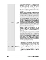
Table 8: remaining in Ready Mode 

Summary of Contents for PS-3185SH

Page 1: ...sing all safety devices supplied Please note that this guide has been written for properly trained Autostart technicians a certain level of skills and knowledge is therefore assumed Please review the Installation Guide carefully before beginning any work Warning This Remote Car Starter is designed for vehicles with a manual Transmission only Before installing the Unit test that the OEM Door Switch...

Page 2: ... the installation of the Remote Car Starter Most of the features of this product are explained in the User Guide Therefore if you need detailed information about a feature of the product we recommend that you refer to the User Guide Included in the Kit Please carefully read the Installation Guide before beginning the installation especially the Harness Description section and the Programming Optio...

Page 3: ...ys leave a window open Never leave the keys in the car Leave them on a workbench with a window rolled down If possible remove courtesy light fuse to prevent battery drain The PROGRAMMING ASSISTANCE BUTTON PAB The PAB is mounted on the side of the Remote Car Starter unit and fulfils the same function as the Hood Pin Switch The PAB will spare installers the effort of getting out of the vehicle to ac...

Page 4: ...nnections Should the Unit be powered up before being grounded there could be serious damage to internal components of the Unit Be careful not to power up a Remote Car Starter before it is properly grounded To avoid any accident it is recommended to pull out the Fuses from their sockets before the installation and to put them back during the very last steps 6 Pin Main Ignition Harness Wire Colour F...

Page 5: ...ecessary Do not jump wires at the Ignition Switch this would compromise the OEM electrical system This high current output can be used to power a second Ignition Accessories or Crank wire See Jumper Setting later in this Guide for correct output F GREEN Fifth Relay output 30 A Please note additional Ignition Accessories or Starter wires must use external relays Do not jump wires at the Ignition Sw...

Page 6: ...rease or increase when the dimmer control switch is turned If the voltage goes up or down find another Parking Light wire 12 Pin Accessories Harness Wire Colour Function Description 1 BLUE Trunk AUX 3 output 500 mA negative output This output can be used to control the Trunk release 1 sec pulse or it can be set to operate as a constant output as long as the TRUNK button is held pressed for Sunroof...

Page 7: ...e by itself a sufficient connection 7 WHITE ORANGE Starter Kill output armed output This wire will provide a constant 500 mA output when the system is armed locked by remote control It can be connected to an external Starter Interrupt Relay This wire should be connected to a Single Pole Double Throw Relay this wire will connect to Pin 85 on the Relay and Pin 86 will be connected to the Ignition wi...

Page 8: ...s enabled UNLOCK pulse s will be sent with disarm a lock pulse and a rearm pulse will be sent when the Trunk is closed or if the Trunk was left closed Option 2 Default Engine Start Stop The first Ground pulse on this input will start the Engine the second Ground pulse on this input will stop the Engine Option 3 Key Sense Input Connects to OEM Key Sense Wire When the Key is detected in the Ignition...

Page 9: ...them simultaneously It is essential that the Remote Car Starter be connected in such a way as will allow each one of the Doors to turn off Ready Mode the driver side Door Pin does not constitute by itself a sufficient connection 12 YELLOW Glow Plug input In Diesel Mode this positive input will monitor the Glow Plug Light it will wait for up to 18 seconds until the Glow plug Light goes out before a...

Page 10: ... using relays to invert the polarity A diode must be added between the negative Glow plug trigger on the relay and the negative Glow plug wire of the car This is to prevent feedback effects on the Glow plug indicator light on the instrument cluster the light on the dash would come on because of the feedback even though the circuit is off When the user remote starts the vehicle The Remote Car Start...

Page 11: ...be programmed for one of the following Options Constant while the LOCK and UNLOCK buttons are pressed simultaneously 1 sec after the buttons are released Pressing LOCK and UNLOCK simultaneously toggles the output ON and OFF with automatic toggle OFF after 30 seconds 2 YELLOW Parking Light output 500 mA negative Parking Light output Flashing the Hood Pin Switch Flashing the Hood Pin switch is a pro...

Page 12: ...ve up to 20 seconds to select a sub menu If you do not select a sub menu within 20 seconds the Remote Car Starter will exit Programming Mode and you will have to flash the Hood Pin switch once again The Programming Assistance Button A k a the PAB Mounted on the Remote Car Starter this button can be used from within the vehicle instead of the Hood Pin switch in the Engine compartment This will spar...

Page 13: ...ions are designed to facilitate interfacing with all vehicle types See section Table of Programming Options later in this Guide 1 Flash the Hood Pin switch see Table 1 The Parking Lights will stay ON for up to 20 seconds Before the lights go out 2 Press and hold the Brake Pedal And press one of the following buttons on the Transmitter LOCK to access Mode 1 UNLOCK to access Mode 2 TRUNK to access M...

Page 14: ...ssive or Active Arming OPTION 1 PASSIVE Arming 60 sec OPTION 2 ACTIVE Arming OPTION 3 PASSIVE Arming 3 min FUNCTION 4 Door lock pulse timing OPTION 1 7 10 sec Lock Unlock pulses OPTION 2 4 sec Lock Unlock pulses OPTION 3 7 10 sec Lock pulse and two 1 4 sec Unlock pulses OPTION 4 1 10 sec Lock Unlock pulses FUNCTION 5 LED flashing OPTION 1 ENABLED without starter kill Æ will flash only when ignitio...

Page 15: ...firmation when lock OPTION 4 Priority Door Access FUNCTION 5 External Trigger OPTION 1 Zone 3 disarm rearm Trunk Pin a disarm pulse is sent before the Trunk opens the vehicle rearms 4 seconds after the Trunk is closed OPTION 2 Engine Start Stop OPTION 3 Key Sense Tach Programming About Tach Programming If you press the START button before carrying out a Tach Programming procedure the Remote Car St...

Page 16: ...ly made and that the Remote Car Starter is powered up 2 With the Hood up ground on the Hood Pin switch line start the vehicle using the Key 3 Allow the vehicle to reach regular Engine idle speed The Parking Light output from the Remote Car Starter will activate when the vehicle starts and shut off once a Tach signal is detected 4 Press the Brake Pedal and keep it down until you hear the Parking Li...

Page 17: ...e system to Ready Mode 1 Ensure that all the Doors are closed and that the Gear Shift Lever is in the NEUTRAL position 2 With the Engine already running apply the Parking Brake and release the Brake Pedal Make sure to release the Brake Pedal 3 Within 20 sec push LOCK UNLOCK or START on the Transmitter The Parking Lights will flash 3 times quickly and remain lit 4 Remove the key the Engine will go ...

Page 18: ...e should not start If the Engine starts rewire the Starter Kill to reach proper operation Valet Mode Make sure the Remote Car Starter is able to properly enter and exit Valet Mode When setting the Remote Car Starter into Valet Mode pressing the Lock button will lock the Doors without activating the Starter Kill Refer to the User Guide for further information on Valet Mode Idle Mode Make sure the V...

Page 19: ... moment you touch the pedal whereas a Clutch switch reacts only when the pedal is near the floor Once the circuit type is determined you must recreate with the Remote Car Starter the electrical interaction occurring at the switch in order to bypass the Clutch at the moment of remote starts Relays are often used to accomplish this Always use the Ground Out When Running G O wire as the negative trig...

Page 20: ...tion and engage the start motor with out pressing in the clutch pedal If there is nothing else connected to the Ground Out When Running G O wire from the Remote Car Starter the G O wire should be strong enough to trigger the vehicle s clutch relay If there are other devices or modules connected to the G O Wire a relay and diodes may have to added to strengthen the negative current going to the clu...

Page 21: ...was in the IGNITION ON RUN position and that the Brake Pedal was pressed at least once Secure Lock This feature allows the Remote Car Starter to control certain OEM factory Alarm systems without requiring the use of other wires for disarming the OEM Alarm Namely this feature is designed for OEM systems which use the factory Lock wire to arm the Alarm and the Unlock wire to disarm it Standard Secur...

Page 22: ...automatically if it is not armed by remote within a 60 sec delay Press UNLOCK to disarm Passive Arming with 3 minute timeout the Starter Kill will arm automatically after 3 minutes Resetting the Remote Car Starter The Remote Car Starter is equipped with a reset function that allows the installer to erase all Transmitter codes from memory and return all the Programming Options to the factory defaul...

Page 23: ...ush the Pin switch 3 more times down up down up down up The Parking Lights and L E D will flash the five events stored in memory Table 12 Events playback The first four playback codes are Start Failure Events There is a pause after each event code is played back The system will play back the most recent event first then the second one and so on If there is no event at all to report the Parking Lig...

Page 24: ...e 2 pause 2 There was an attempt to start the vehicle while the Remote Car Starter was in Home Valet Mode 4 pause 3 The vehicle went out of Ready Mode 12 V detected on the Brake Line 10 pause 3 The vehicle went out of Ready Mode the Hood Pin switch went to ground ON 2 sec The Hood is up and the Hood Switch line went to ground This is step one of the Programming Centre procedure ON 3 sec First pres...

Page 25: ...PS 3185SH Wiring Diagram PS 3185SH Installation Guide ...

Reviews: