background image

DD-75-181 R(2)


Y.T.13.07.17

7

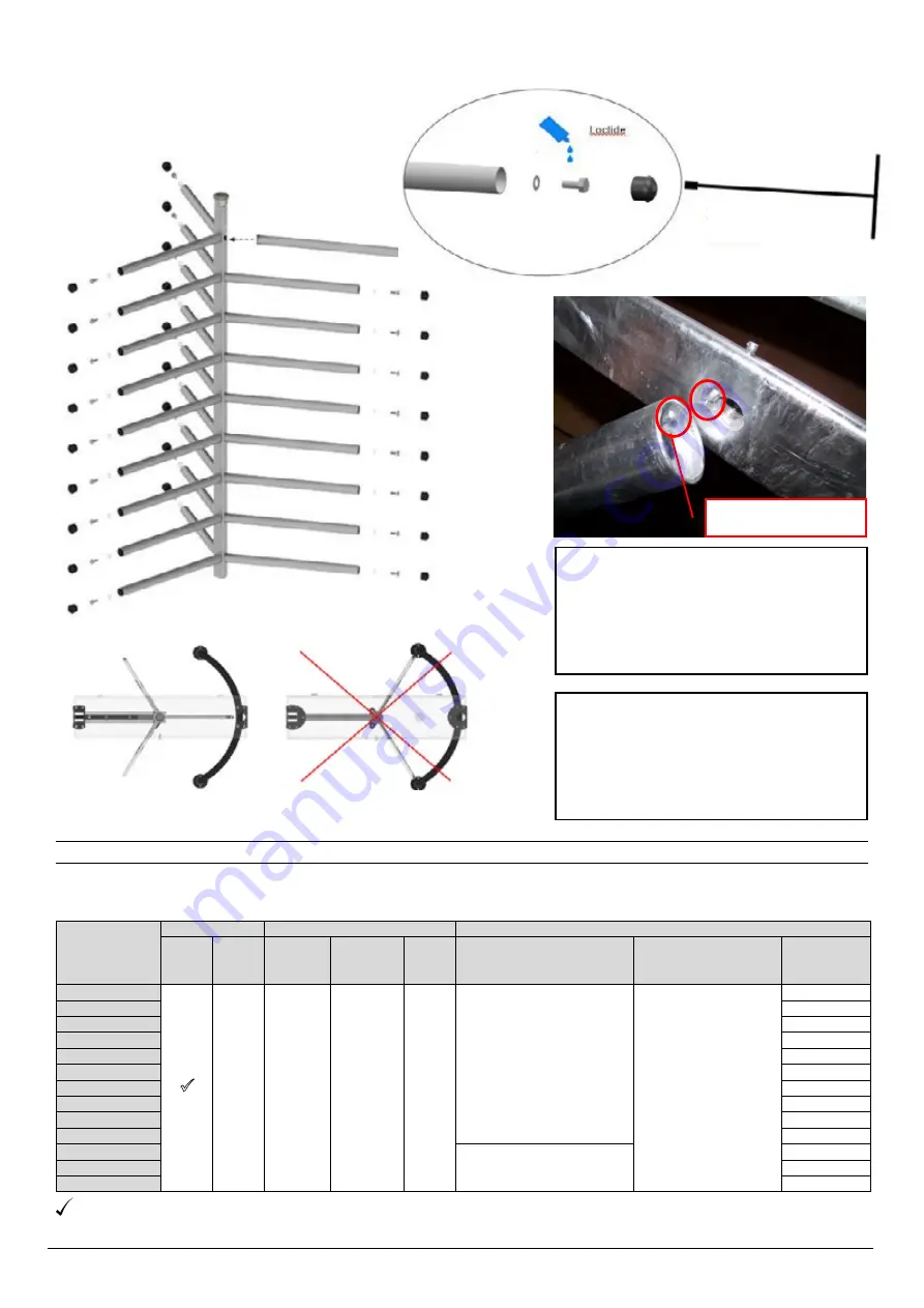
3.3  Mounting of Arms 

Caution! 

Arms can loosen and fall 

if not mounted correctly.

Kilitleme pimleri


Attach arms on the rotor and turn counter 
clockwise until lock pins are engaged to 
prevent removal of the arms by turning. 

Fully tighten arm bolts (apply loctide) and 

install arm caps by tapping with a rubber 
hammer.

Lift the mechanism channel at one end to 

correctly adjust rotor position and re-seat 
it on the rotor coupler. Refer to detailed 

assembly instructions supplıed with each 

turmstile model.

19 mm socket wrench 
with long handle

Mounting of Arms

   Incorrectly Installed Rotor

  Correctly Installed Rotor

4. TURNSTILE SYSTEM SPECIFICATIONS


4.1 Full Height Turnstile Table of Specifications

Lock pins

Manual

Motor

Driven

Movement Lock Control

Stop

Structural Materials

Rotor

&

Arm

Arm 

Configuration

BT 312 S / D

3 Arms (120

˚

)

BT 402 S / D

4 Arms (90

˚

)

BTE 312 S /D

3 Arms (120

˚

)

BTE 402 S / D

4 Arms (90

˚

)

BTX 100

1 Arm (90˚+90˚)

BTX 300 S / D

3 Arms (120

˚

)

BTX 400 S / D

4 Arms (90

˚

)

BTA 300 *

3 Arms (120

˚

)

ECOLINE 300 S / D

3 Arms (120

˚

)

ECOLINE 400 S / D

4 Arms (90

˚

)

BT 302 GL *

3 Arms (120

˚

)

BT 400 GL *

4 Arms (90

˚

)

BT 402 GL *

4 Arms (90

˚

)

MODEL

-Glass (Side Walls)

-Aluminium

-304 / 316 Grade Stainless Steel

Mechanism

Operation

Materials

H

yd

ra

u

lic

 Da

mp

er

-Hot Dip Galvanized Steel

-Hot Dip Galvanized and

Electrostatic Powder Coated 

Steel

-304 / 316 Grade Stainless 

Steel

-Acrylic (arm,for BTA300)

9

Ο

Push to 

Rotate

(Optional 

Motorized)

Solenoid

­

Hot Dip Galvanized Steel

-Hot Dip Galvanized and

Electrostatic Powder Coated Steel

-304 / 316 Grade Stainless Steel

  : Standard

Ο  : Optional

* :  Opt. different materials

Summary of Contents for BT 302 GL

Page 1: ...OIME _ I I FULL HEIGHTTURNSTILE INSTALLATION ANID MAINTENANCE HANDBOOK www polimek com tr...

Page 2: ...DD 75 181 R 2 Y T 13 07 17 2...

Page 3: ...SETUP AND OPERATION 9 5 1 Power and Ground Connections 5 2 Control Board Connections 5 3 Wiring Diagrams 5 3 1 Control Board Terminals 5 3 2 Internal Wiring Diagram 5 4 Control Board Settings 5 4 1 I...

Page 4: ...on Turnstiles Turnstiles are devices that enable passage control and prevent uncontrolled or unauthorized passages in stadiums sports halis leisure facilities business centers public transportation a...

Page 5: ...and fuse values when performing any work on the turnstile Warning labels and power supplies may vary depending on the turnstile model and type WARNING To avoid shock hazard AC power connections must b...

Page 6: ...erating Conditions 1 More than one person must not attempt to pass at the same time 2 Turnstile must not be forced kicked abused or tempered with to gain passage without authorization 3 Turnstiles mus...

Page 7: ...eight Turnstile Table of Specifications Lock pins Manual Motor Driven Movement Lock Control Stop Structural Materials Rotor Arm Arm Configuration BT 312 S D 3 Arms 120 BT 402 S D 4 Arms 90 BTE 312 S D...

Page 8: ...ides dry contact relay output for each direction An optional counter can be used 14 Electronic control unit of the turnstile is protected against water for outdoor installations 15 Turnstiles can work...

Page 9: ...FUSE 3A ERT N F FUSE Warning Power and grounding connections must be made by a qualified electrician in accordance with the relevant local regulations using appropriate materials Proper grounding mus...

Page 10: ...et and cable tumber tags when replacing board and other parts 3 Connect cable leads into the screw type connector Passage Confirmation Relay NO Normally B A Open Dry Contact Com Control lnput Terminal...

Page 11: ...n collector input 8 8 8 8 8 8 Optional counter 1N4001 or similar Busy Out or or TRN1202 0 5 1 sn busy B A A B Enable Gnd Passage confirmation dry contact output Use with access control systems counter...

Page 12: ...3 External Module Connector Motor Driver Drop Arm Control etc 14 Enable Disable inhibit A Board Serial Number B Stock Code C Production Number D Board Model SN Res 24V B A A B N O N O Com Com Gnd Gnd...

Page 13: ...turnstile for one way passage 5 4 2 Dip Switch Settings Time out and mode settings of the turnstile are selected by the dip switch located on the control board as explained below 1 Bi directional cont...

Page 14: ...the mechanism 5 5 Hydraulic Damper Adjustment Manual Models Note Damping factor is increased when dial is turned clockwise Once the adjustment is done tighten the stop screw while holding the dial st...

Page 15: ...ilable appropriate metal polishing compounds can be used for removal of tougher stains The recommended frequency of cleaning depends on the local environment as explained in table below Do not wash th...

Page 16: ...chnical Service Personnel Description of Fault Possible Cause Recommended Action No power indicators buzzer locks off Rotor free wheels when power is on Note Ensure Emg terminal is not activated and d...

Page 17: ...Faulty motor 1 Loose photo sensor connector 2 Misaligned bent or contaminated photo sensor 3 Faulty photo sensor 1 Too low motor speed setting on motor driver board 2 Loose or oil contaminated drive...

Page 18: ...DD 75 181 R 2 Y T 13 07 17 18 7 3 Mechanism Assembly Exploded Diagrams...

Page 19: ...lenoid 5V 20 02 02 0323 20 02 03 0027 10 00 10 0023 20 02 07 0013 20 02 07 0029 20 03 01 0399 30 01 14 0006 10 09 02 0001 10 02 00 0001 10 00 10 0001 20 02 00 0041 20 02 00 0098 30 01 01 0020 10 01 23...

Page 20: ...LES HALF HEIGHT TURNSTILES PEDESTRIAN GATES SPECIAL DESIGN TURNSTILES FREE PASSAGE RETAIL LINE TURNSTILES lgili Direktifler Relevant Directives 2006 42 EC Makine Emniyet Y netmeli i Machine Safety Dir...

Page 21: ...ollowing the date of purchase excluding failures resulting from physical damage incorrect installation misuse tampering and similar reasons beyond manufacturers control 1 Any tampering or damage on wa...

Page 22: ...DD 75 181 R 2 Y T 13 07 17 23...

Reviews: