background image


Politec S.r.l. | Manual Ales – Ver. 1.7.2 

10 


3.


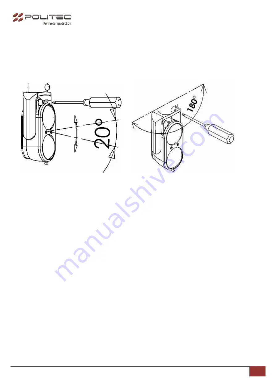
Align the optics placed in the column TX to RX, vertically and horizontally by turning the adjustment 
screws (horizontal and vertical) to find the maximum alignment. The condition of maximum alignment will 
be achieved when the LEDs are fixed and the buzzer will sound continuously. The condition of partial or 
total misalignment is indicated by flashing LEDs and low frequency whistle of buzzer. 
 

► Buzzer sounds continuously for max 3 minutes 


To get a good alignment is necessary to make a complete rotation on the optics receiver 
horizontal axis, thus effecting the SCANNING of the optical signal. 


4.


After obtained the calibration tighten the screw for horizontal adjustment, and exit from TEST mode by 
pressing the TEST button for 3 seconds on RX mother board. Two beeps of buzzer will indicate the end of 
the TEST function.


► 

After adjusting for the next 3 minutes each alarm event will be highlighted by a beeper


1.Vertical adjustment 

2. Horizontal adjustment 

Summary of Contents for ALES 120

Page 1: ...INFRARED PERIMETRAL BARRIER DOUBLE BEAMS...

Page 2: ...Pag 14 Installation recommendation Verify that the beam tower is fully watertight once the cover and end caps have been correctly filled at the end of the installation The missed used of proper access...

Page 3: ...AIN COMPONENT LIST 1 Terminal Block 2 Channel selector 3 TEST button 4 Tamper Switch 5 Horizontal adjustment screw 6 Adjustment Buzzer RX 7 Adjustment high frequency led RX 8 Vertical adjustment screw...

Page 4: ...Politec S r l Manual Ales Ver 1 7 2 4 MOUNTING PLATE U BRACKET FOR POLE MOUNTING IR COVER...

Page 5: ...original accessories In case of repairs covered by warranty 2 years but with obvious signs of improper installation the Politec s r l reserves the right to decide on any repair costs Avoid installing...

Page 6: ...d power cable 12Vdc ex 2x0 5 8x0 22 with the metallic shield connected to ground to prevent the introduction of disturbances of the alternating voltage on the barrier The cable size depends on the con...

Page 7: ...ONTACT N C only RX 2 3 TAMPER CONTACT 4 5 GND 6 POWER SUPPLY 10 30 Vdc 4 DIS ON only RX With inserted jumper enables the environmental disqualification and the monitoring output Dis Out 5 CHANNELS SEL...

Page 8: ...ifferent channel to each of them To do this you must turn ON dip switches on the desired channel on the mother board The channel will be the same from both the transmitter from the receiver ex CH_TX1...

Page 9: ...GNMENT TEST Press the TEST button on the RX mother board for 3 seconds until the buzzer will beep twice accompanied by two blinking of LEDs to begin calibration 1 Press the TEST button on the RX Colum...

Page 10: ...and low frequency whistle of buzzer Buzzer sounds continuously for max 3 minutes To get a good alignment is necessary to make a complete rotation on the optics receiver horizontal axis thus effecting...

Page 11: ...EST button to exit the alignment mode and wait for the two consecutive beep of the buzzer If you need the standard 50 ms delay time is not necessary to continue to the next step but wait for the confi...

Page 12: ...on mode Press the TEST until 2 BEEP to have 250ms intervention time Continue to press the TEST button until the 4 BEEP to have 750 intervention time Double BEEP confirm the alignment done Perform the...

Page 13: ...on for which the barrier is in a standby state this will avoid annoying false alarms caused by weather conditions 9 ADDITIONAL TAMPER On mother boards TX and RX there is a supplementary Tamper input u...

Page 14: ...squalification Yes with open collector output Setting intervention time 4 settings Power supply 10 30Vcc Operative current consumption 90mA Heaters consumption couple Optional with thermostat 10 30V 1...

Page 15: ...rnal lights are interesting RX side during function TEST gate photocell any other barrier infrared lights exc o Use a screened cable to supply barriers connecting screen to GND on terminal block it is...

Page 16: ...cables one to supply and one for alarm tamper output o Check correct dimension of cable used to supply barriers o It is possible to increase barrier screening connecting to GND a cable coming from the...

Reviews: