background image

28

POLITEC | INSTALLATION MANUAL - VER.3.1

RX 1

TX 1

RX 2

TX 2

RX 3

TX 3

RX 4

TX 4

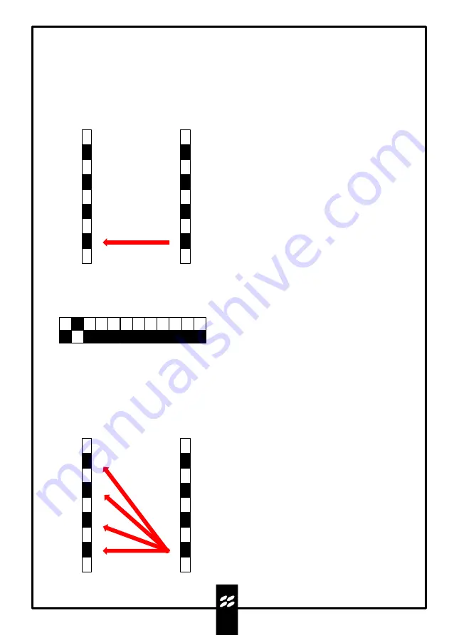
N.B.:During the alignment test phase, the
activation of a TX transmitter determines the
automatic shutdown of the other TX optics in
the column.

16.3 Parallel beam calibration

Test the TX1 and RX1 optics and proceed with the calibration as explained.Then repeat the operation
for each pair of optics.

16.4 Calibration with active crossing function

To activate the function, move DIP 2 of the 12 DIPSWITCH unit of the MES9012 in ON.

RX 1

TX 1

RX 2

TX 2

RX 3

TX 3

RX 4

TX 4

ON

1

2 3 4 5 6 7 8 9 10 11 12

Test the TX1 and RX1 optics and proceed with the calibration as explained above but, having found the
maximum alignment, keep the TX1 optic in test and exit the test only with RX1, then repeat the same
operations with RX2, RX3 and RX4.
At the end, exit the test of TX1 and repeat the operation for each TX optic on each RX.
At the end of all operations, make sure that TX1 and TX4, being at the ends and most susceptible to 
orientation movements, are still optimally aligned with the corresponding RX1 and RX4.

MANA DT SMA 

WARNING

: too close a distance

between the TX and RX columns does
not allow calibration with the crossing
function.

Summary of Contents for MANA DT SMA

Page 1: ...PRODUCT MANA MANA DT SMA Product code MANA DT SMA DOUBLE TECHNOLOGY AND RS485 OUTPUT PERIMETER BARRIER INSTALLATION AND MOUNTING MANUAL VERSION 3 1...

Page 2: ...troduction to barriers MW section 9 2 Introduction to barriers IR section 11 Barrier positioning 15 11 1 Precautions before installation MW section 11 2 Precautions before installation IR section 11 3...

Page 3: ...onents 23 2 LED signal operation 23 3 Features and settings 24 Appendix D configuration of optical boards 39 24 1 Transmitter optic 24 2 Receiver optic 25 Appendix E configuration with 3 2 receivers 4...

Page 4: ...u must make the connection wired or in barrier or in the control unit WARNING In the case of operation in AND do not activate the fog disqualification function in the IR section This barrier is ideal...

Page 5: ...there is no warranty for the end user who in the event of breakdowns or faults must contact the installer or dealer The warranty excludes aesthetic parts as well as parts subject to normal wear and pa...

Page 6: ...enna and cavity at 24GHz 9 Aluminium profile 10 Heaters 11 12Vdc 24Va power supply boardc 12 Mana 160VA transformer 13 Polycarbonate black screen 14 Anodised anticorodal aluminium disk 3 2 5 4 1 7 9 6...

Page 7: ...eless models with universal electronic board housing insert and connect the radio transmitter and connect it to the barrier receiver board cc Power up the barriers and program them d Test barrier oper...

Page 8: ...stallation Insert the edge shown in the figure into the slot on the other wall and fix everything with the screws Insert the third side in the same way and tighten the screws Widen the two opposite wa...

Page 9: ...pit Positioning must take place perpendicular to the ground If the base is not perfectly level minor adjustments can be made by adjusting the inserts on the cable pit By loosening the insert on the ap...

Page 10: ...te 1 plate 2 black insulating sheath 4 barrier anchor screws Insert the 60mm screw in the perforated plate and tighten the locking bolt Insert a sheath the transformer the second sheath and the plate...

Page 11: ...ase with sealing OR for cable entry with cable glands Once the necessary cables have been passed through the bottom cover is fixed with the screws supplied along with the corresponding gasket At the e...

Page 12: ...ac FUSE B 0 8A 13 8Vac Red Red Black Black Blue Brown red red black black brown blue Make all electrical connections as shown on the diagram HEATER HEATER To IR board MES 9012 flat cable To the TX or...

Page 13: ...columns the width of which in the centre reaches up to 4 5m The most peripheral part is called the SENSITIVE ZONE while the most central part is called the ALARM ZONE View from above Signal interrupti...

Page 14: ...ve multiple controls that significantly limit false alarms as the genuine alarm signal is given by the complete interruption of the infrared signal HEATERS It is recommended to power the thermostating...

Page 15: ...es and fences to avoid wave reflections that would cause abnormal operation with generation of alarms MANA DT SMA It should also be considered that due to the effect of the generated lobe there is a d...

Page 16: ...ers if there are plants bushes or fixed objects in the range that obstruct the signal and create grey areas Leave a corridor of 50cm for distances between columns greater than 50m TX RX TX RX DO NOT p...

Page 17: ...factors the choice of the dual technology barrier offers a significant advantage in terms of reliability in addition to the considerable reduction of possible false alarms E g heavy snow growth of gra...

Page 18: ...ly of the SHIELDED type e g Nx0 22 mm minimum to transfer all the output signals of the individual columns to the alarm control unit in addition to the synchronism connection between the columns other...

Page 19: ...e transformer 3 4 13 8 V outputcc Infrared section power supply 5 6 24 Vac input Cable coming out of the transformer 7 8 24 Vac output Heater power supply 13 Connections to the MANA AL 214 power suppl...

Page 20: ...charging limit is 0 25 A 5 Heater fuse 5 A delayed to protect the heating circuits 6 Circuit fuse 0 8 A delayed to protect the MW TX or RX and IR circuits 7 Jumper J7 If inserted the 24Vac output of t...

Page 21: ...closed ALARM RELAY NC 6 17 DISQUALIFICATION OUTPUT S LOW Normal conditions high impedance with fog negative voltage Alarm output Common ALARM RELAY COM 7 18 ANTIMASKING OUTPUT A MASK Normal condition...

Page 22: ...bly separated from the power supply with the braid connected to the negative The synchronism connections between the columns can be made directly in the control unit or in a branch junction box By usi...

Page 23: ...s possible as it is not possible to make horizontal movements but only vertical corrections with the dish antenna Permanently fix the columns and perform the following steps MANA DT SMA 1 Activate the...

Page 24: ...ain again to have only the red and yellow LEDs on Gain trimmer anticlockwise 8 Increase the signal level again by rotating the RX and TX columns horizontally and vertically using the locking screw beh...

Page 25: ...e lens Vertical orientation Horizontal orientation JOINT LOCKING SCREW N B Tighten the joint locking screw after making the adjustment 16 1 Calibration using SMA system It is possible to improve the c...

Page 26: ...y of signal received Press the TEST button on the TX optic of the corresponding column for 5 seconds in this case only the orange TEST LED will light up Orient the TX optic towards the RX optic vertic...

Page 27: ...of the LEDs and by the non continuous whistle of the buzzer After calibration tighten the horizontal adjustment screw and exit the test function by pressing the TEST button on the TX and RX optics fo...

Page 28: ...n ON RX 1 TX 1 RX 2 TX 2 RX 3 TX 3 RX 4 TX 4 ON 1 2 3 4 5 6 7 8 9 10 11 12 Test the TX1 and RX1 optics and proceed with the calibration as explained above but having found the maximum alignment keep t...

Page 29: ...ame both on the TX and on the RX board 17 Optical synchronism 1 2 3 4 RX channel ON 1 2 3 4 TX channel ON 1 2 3 4 5 6 7 8 9 10 11 12 Set DIP 4 to OFF ON MANA DT SMA N B Optical synchronism requires gr...

Page 30: ...se alarms Low risk of non detection DLY Turn clockwise to decrease system sensitivity High requires a large mass to generate alarm Low requires a small mass to generate alarm 18 Basic functions MW sec...

Page 31: ...SSION AND RECEPTION RX 1 by default normal operation all ON forced closed alarm relay TX 1 by default normal operation all OFF all TXs turn off 12 DIP UNIT FOR CONFIGURATION INTERVENTION TIME ADJUSTME...

Page 32: ...justing the potentiometer anticlockwise the intervention time is increased up to 500ms In this condition the alarm of a person crossing the barrier while walking is guaranteed with the advantage of ex...

Page 33: ...imeter to be protected If the installation spaces do not allow the correct positioning of the columns the use of the DT3 sensor is recommended which uses a 24GHz microwave with Doppler effect This is...

Page 34: ...isturbance Intermittent buzzer sound Disturbance absent Buzzer sound absent 22 2 Function DIP MW RX board 1 LEDS It activates the LED bars 2 FIELD It displays the signal value on the LED bar 3 OPEN It...

Page 35: ...W Green 5 HEATERS LED HTR Yellow 6 SYNCHRONISM SYNC Yellow 7 TRIMMER Intervention time adjustment 8 J7 DISQ1 9 12 DIP SWITCH UNIT Function selector 10 4 DIP SWITCH UNIT TX Function selector 11 4 DIP S...

Page 36: ...at masking N B In normal operating conditions the LED must remain off If it remains on or flashing check the correct setting of the beam selection jumpers on the various transmitters of the other col...

Page 37: ...is function remotely DIP6 must remain OFF 7 BEAM OFF 1 In the ON position the first beam at the bottom is excluded while the rest continue to work The function can also be programmed remotely by givin...

Page 38: ...ism operation with transmission frequency 4 only 2 transmitters are active 4 DIP SWITCH UNIT TX TERMINAL TX ONLY All DIP switches are ON the alarm relay is deactivated This setting is used when the co...

Page 39: ...IP 7 in ON as default and with the power supply LED on the TX optic functioning is verified The power supply of the heaters is set by default to 24V this voltage is supplied directly by the power supp...

Page 40: ...ified The power supply of the heaters is set by default to 24V this voltage is supplied directly by the power supply present in the MANA series columns Jumper J4 reads the value of the alignment signa...

Page 41: ...in the column is set as follows ON RX3 ON RX2 ON TX2 ON TX3 ON RX4 ON TX4 1 2 3 4 5 6 7 1 2 3 4 5 6 1 2 3 4 5 6 7 1 2 3 4 5 6 25 2 Setting of models with 2 Beams The DIP SWITCH setting on the optics i...

Page 42: ...tem it is MANDATORY to use wired synchronism N B It is possible to use the two additional wires of the bus cable for synchronism red black pair 26 1 Serial port connection and synchronism for each bar...

Page 43: ...the IR barrier is composed of 6 or 8 beams as shown below With a maximum number of 4 beams only set DIP 1 to ON on all 4 DIP units RX channel 1 2 3 4 ON 1 2 3 4 TX channel ON Barrier 1 Barrier 2 RX c...

Page 44: ...ectronic on display ON BOARD MW FREQUENCY 24GHz K band with 4 switchable channels MW LOBE WIDTH 4m half section 250m MW SENSITIVITY ADJUSTMENT ON BOARD alarm threshold detection mass CIRCUIT POWER SUP...

Page 45: ...ecking that the orange LEDs are off Make sure that the connectors are well inserted and that the DIP configuration is correct Check that the power supply on the terminal board is sufficient Use the sh...

Page 46: ...the lenses in order to have two surfaces interposed between TX and RX to double the attenuation of the beam Repeated false alarms Check the alignment accuracy of each individual optic and if necessar...

Page 47: ...al systems for this category of products governed by regulations in force in your area Warning Some parts of the products may contain polluting or dangerous substances which if dispersed in the enviro...

Page 48: ...MANA DT SMA POLITEC INSTALLATION MANUAL VER 3 1 For technical support contact your security systems distributor 48...

Reviews: