background image

13

SADRIN WS SMA

POLITEC | INSTALLATION MANUAL - VER.2.1

8.3 Expansion board wiring

If inserting or removing expansion boards, make sure they are connected in the correct direction.

9.Programming and commissioning

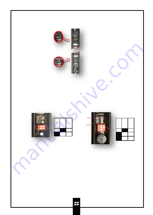
9.1 Powering the barriers

Connect the power supply to the dedicated input respecting the polarity and check the flashing of the
LED.Power first the TX column and then the RX column.

9.2 Checking alignment and operation

DL1 
RED LED

DL2
BLUE LED

TX

RX

O

FF

ON

1
2
3

O

FF

ON

1
2

1.

Set the TEST DIP 1 of the TX motherboard to ON.

2.

Set the TEST DIP 1 of the RX motherboard to ON. 

3.

In this phase, the barrier alignment takes place, where each RX optic receives the signal from 
the corresponding TX optic, the maximum value is reached when the BLUE test LED and the 
buzzer provide a continuous signal.

4.

To exit the test, set TEST DIP 1 to OFF on the RX, the RED LED will flash and the WALK TEST
function will activate for a duration of 30'', the barrier will emit a continuous acoustic signal in
the event of interruption of one beam (two beams if configured in AND) to indicate the correct
operation of all optics.The BLUE LED will flash if the tampers are open.

5.

At the end of this phase, the BLUE TEST LED will light up and the RED LED will flash until the 
TEST DIP 1 on the TX motherboard is set to OFF.

Expansion boards codes: 

SADRIN ESP WS RX/SADRIN ESP WS TX

Summary of Contents for Sadrin WS Series

Page 1: ...PRODUCT Sadrin WS SADRIN WS SMA Product code Sadrin WSI SMA Sadrin WSE SMA Self powered Wireless Mini barrier INSTALLATION AND MOUNTING MANUAL VERSION 2 1...

Page 2: ...llation 7 5 1 Preparation of the barrier parts before installation 5 2 It is advisable to carry out 6 Mounting fixing instructions 8 6 1 Placement and installation height 6 2 Mounting 7 Batteries 11 7...

Page 3: ...ter barrier consists of an infrared receiver and transmitter Operation is based on AND logical operations in other words the alarm is activated only in the event of simultaneous interruption of two su...

Page 4: ...m Politec there is no warranty for the end user who in the event of breakdowns or faults must contact the installer or dealer The warranty excludes aesthetic parts as well as parts subject to normal w...

Page 5: ...ycarbonate cover 3 Aluminium profile 4 Optic 5 CPU WS TX RX motherboard 6 Batteries 7 Flat cable for board connection 8 ESP WS TX RX expansion board 4 2 6 1 3 5 7 1 4 1 SADRIN WSI version 8 The WSI ve...

Page 6: ...r board connection 9 CPU WS TX RX motherboard 10 ESP WS TX RX expansion board 11 Standard cap 5 2 1 4 6 4 2 SADRIN WSE version 3 7 8 9 11 10 The WSE version has a box at the head of each TX and RX col...

Page 7: ...iversal circuit board housing insert and connect the radio transmitter and connect it to the barrier receiver board c Power up the barriers and program them d Test barrier operation e Place without fi...

Page 8: ...nto account the diffusion of the infrared beam to avoid reflection of the beams caused by adjacent shiny surfaces If possible position the barrier so that sunlight does not hit the RX column directly...

Page 9: ...al grooves on the cap and on the cover to allow the cable to pass from outside the barrier RECESSED CABLE ROUTING EXPOSED CABLE ROUTING Round grooves on the bottom for cable routing Grooves on the wal...

Page 10: ...lly after fixing the box on the upper part of the columns Adjustment holes WSE WSI At the end of the installation and alignment process close the cover with the supplied screw N B The barriers in the...

Page 11: ...2 years 1 year value refers to 2 batteries 3 6 V 2 7 mAh value refers to 4 batteries 3 6 V 2 7 mAh value refers to a 3 6 V 19 Ah battery N B The low battery signal occurs as a local acoustic alert du...

Page 12: ...ector WSE 3 6 V 19 Ah Additional tamper input WSE if absent leave closing jumper TX Battery connector WSE 3 6 V 19 Ah Additional tamper input WSE if absent leave closing jumper Voltage selector for TX...

Page 13: ...ON 3 In this phase the barrier alignment takes place where each RX optic receives the signal from the corresponding TX optic the maximum value is reached when the BLUE test LED and the buzzer provide...

Page 14: ...YSTEM with 15mm lenses in AND Optical sensors Pulsed type beams with a wavelength of 950 nm Max configuration 2TX 2RX 4TX 4RX 6TX 6RX 8TX 8RX Beam arrangement Parallel Power supply Lithium Batteries 3...

Page 15: ...part of the equipment and must be disposed of together with it Just as with installation operations also at the end of life of these products the dismantling operations must be carried out by qualifie...

Page 16: ...POLITEC INSTALLATION MANUAL VER 2 1 For technical support contact your security systems distributor...

Reviews: