background image

6.Mounting/fixing instructions

8

SADRIN WS SMA

POLITEC | INSTALLATION MANUAL - VER.2.1

6.1 Placement and installation height

This type of Active Infrared Beam barriers is always made up of a pair of columns, one is a TX
transmitter only and the other a RX receiver only.The barrier is self-powered with batteries already
included, and must be combined with a radio transmitter of any brand of Wireless systems on the
market.
Its compact size makes it particularly suitable for single barrier systems to protect windows, doors or
facades of limited dimensions.
Therefore, we advise against installation in open areas unless due precautions are taken.
Position it in such a way that in its range of action there are no obstacles such as: pots on the
windowsills, mosquito nets or objects that can swing or move with the wind.
In any case, it is necessary to take into account the diffusion of the infrared beam, to avoid reflection
of the beams caused by adjacent shiny surfaces.
If possible, position the barrier so that sunlight does not hit the RX column directly.
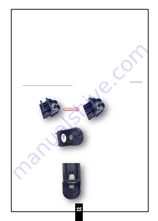
6.2 Mounting

Remove the caps and remove the extruded cover.The barriers are a standard size in terms of
column height but different sizes can be supplied if communicated when ordering.If at this stage,
it is necessary to reduce the length of the profile, it can be cut, taking care to prevent metal slag
from ending up on the electronic circuits.

The barrier in the 

WSI

version can be mounted indifferently with both boards with the terminal 

board, at the top or bottom.

Insert the square gasket into the cap until the joints fit together.

Insert the concentric cable grommet in the appropriate hole.

Make a hole in the concentric gasket, of the lower or upper cap, so that the conical wall exerts a
sealing pressure on the sheath of the connection cable that will pass inside it.

Insert the cap into the aluminium profile until the gasket matches the metal.

Summary of Contents for Sadrin WS Series

Page 1: ...PRODUCT Sadrin WS SADRIN WS SMA Product code Sadrin WSI SMA Sadrin WSE SMA Self powered Wireless Mini barrier INSTALLATION AND MOUNTING MANUAL VERSION 2 1...

Page 2: ...llation 7 5 1 Preparation of the barrier parts before installation 5 2 It is advisable to carry out 6 Mounting fixing instructions 8 6 1 Placement and installation height 6 2 Mounting 7 Batteries 11 7...

Page 3: ...ter barrier consists of an infrared receiver and transmitter Operation is based on AND logical operations in other words the alarm is activated only in the event of simultaneous interruption of two su...

Page 4: ...m Politec there is no warranty for the end user who in the event of breakdowns or faults must contact the installer or dealer The warranty excludes aesthetic parts as well as parts subject to normal w...

Page 5: ...ycarbonate cover 3 Aluminium profile 4 Optic 5 CPU WS TX RX motherboard 6 Batteries 7 Flat cable for board connection 8 ESP WS TX RX expansion board 4 2 6 1 3 5 7 1 4 1 SADRIN WSI version 8 The WSI ve...

Page 6: ...r board connection 9 CPU WS TX RX motherboard 10 ESP WS TX RX expansion board 11 Standard cap 5 2 1 4 6 4 2 SADRIN WSE version 3 7 8 9 11 10 The WSE version has a box at the head of each TX and RX col...

Page 7: ...iversal circuit board housing insert and connect the radio transmitter and connect it to the barrier receiver board c Power up the barriers and program them d Test barrier operation e Place without fi...

Page 8: ...nto account the diffusion of the infrared beam to avoid reflection of the beams caused by adjacent shiny surfaces If possible position the barrier so that sunlight does not hit the RX column directly...

Page 9: ...al grooves on the cap and on the cover to allow the cable to pass from outside the barrier RECESSED CABLE ROUTING EXPOSED CABLE ROUTING Round grooves on the bottom for cable routing Grooves on the wal...

Page 10: ...lly after fixing the box on the upper part of the columns Adjustment holes WSE WSI At the end of the installation and alignment process close the cover with the supplied screw N B The barriers in the...

Page 11: ...2 years 1 year value refers to 2 batteries 3 6 V 2 7 mAh value refers to 4 batteries 3 6 V 2 7 mAh value refers to a 3 6 V 19 Ah battery N B The low battery signal occurs as a local acoustic alert du...

Page 12: ...ector WSE 3 6 V 19 Ah Additional tamper input WSE if absent leave closing jumper TX Battery connector WSE 3 6 V 19 Ah Additional tamper input WSE if absent leave closing jumper Voltage selector for TX...

Page 13: ...ON 3 In this phase the barrier alignment takes place where each RX optic receives the signal from the corresponding TX optic the maximum value is reached when the BLUE test LED and the buzzer provide...

Page 14: ...YSTEM with 15mm lenses in AND Optical sensors Pulsed type beams with a wavelength of 950 nm Max configuration 2TX 2RX 4TX 4RX 6TX 6RX 8TX 8RX Beam arrangement Parallel Power supply Lithium Batteries 3...

Page 15: ...part of the equipment and must be disposed of together with it Just as with installation operations also at the end of life of these products the dismantling operations must be carried out by qualifie...

Page 16: ...POLITEC INSTALLATION MANUAL VER 2 1 For technical support contact your security systems distributor...

Reviews: