background image

www.polkaudio.com

27

Interference

If this unit is placed very near a television, picture disturbance 
or noise may occur on the TV. In such a case, move the RMDS-1 
preamp/processor as far as possible from the television. If the problem
persists, re-route the TV antenna cable so that it is as far as possible
from the power cable and audio and video connection cables of the
RMDS-1 system. Since the phenomenon is most likely to occur when
using a TV antenna with a 300-ohm feeder wire, we recommend using
an outdoor antenna connected via a 75-ohm coaxial cable.

Safe Limits of Operation 

The RM Digital Solution system was made with the highest quality
materials for years of trouble-free performance. However, damage to
the system can occur if the system is played at excessive listening 
levels. When the sound becomes harsh or distorted, you have reached
the safe limit of operation. Turn down the volume until the sound is
clear and undistorted. 

Protection Circuits

The RMDS-1 amplifier features several circuits to protect the 
amplifier and speakers from damage from overheating, shorts, and
other electrical faults. If these protection circuits are tripped, all
channels will turn off, even if the fault occurs on only one channel. 
In such cases, turn off the RMDS-1 preamp/processor, remove the
fault (usually a short on one of the speaker wires where the + and -
wires have touched each other) and turn the system back on again. 
In the case of overheating, allow the system to cool down for about 
15 minutes and re-start the system. Overheating is usually a sign that
the amplifier (in the subwoofer enclosure) does not have enough air
circulation. Move the subwoofer to a less enclosed space.

Maintaining the Appearance of Your System

The preamp/processor and speaker enclosures may be cleaned with a
soft damp cloth or duster. Do not use harsh detergents and cleaning 
fluids, they can permanently damage the finish. Vacuum the speaker
grilles to remove dust. 

Q. “Why does my system hum?”
A.  “It doesn’t know the words.” 

This is what passes for humor in the audio business. 
Here is the real answer.

In some installations you may hear a humming noise from the
subwoofer. Most hum problems are caused by ground loops. That is, the
electrical grounds of the components in your system are not at the
same electrical potential. To help avoid hum problems, make sure that
every component in the audio/video system is plugged in to the same
electrical circuit (not necessarily the same outlet). A common ground
loop source is cable TV. Disconnect the coaxial cable from your TV
and/or VCR. If the hum goes away, the cable TV is the ground loop 
villain. In that case, you need a 75-ohm ground loop isolator. This
device is about the size of a pen and is attached to your coaxial cable
where it plugs into your VCR (or television). You can obtain this device
from some audio dealers, Radio Shack stores, Xantech (1-800-843-
5465) or Channel Plus (1-800-999-5225).

Ground loops and hum can also be the result of faulty electrical wiring
in your home. Consult a licensed electrician to evaluate and, if
necessary, repair the AC wiring in your home. Light dimmers also tend
to introduce noise into audio systems. Remove them.

If none of our suggestions works for you, call our customer service
number shown below.

Technical Assistance or Service 

If, after following the hook-up and use directions and consulting the
troubleshooting chart on page 26, you still have trouble, please call our
cheerful customer service representatives. They are happy to answer
your questions and provide fast, friendly service. In North America call
(800) 377-7655, Monday through Friday, 9:00 AM through 6:00 PM
Eastern time. Or you can e-mail us at our Internet service address:
polkcs@polkaudio.com.

Polk Audio, Inc., warrants to the original purchaser only that the 

Preamp/Processor and Amplifier

in this Polk Audio Loudspeaker

Product (the “Product”) will be free from defects in material and
workmanship for a period of three (3) years from the date of original
retail purchase from a Polk Audio Authorized Dealer. Polk Audio, Inc.,
further warrants to the original purchaser only that the

Loudspeaker(s)

in this Polk Audio Product (the “Product”) will be free

from defects in material and workmanship for a period of five (5) years
from the date of original retail purchase from a Polk Audio Authorized
Dealer. However, this Warranty will automatically terminate prior to the
expiration if you sell or otherwise transfer the Product to any other
party. The original retail purchaser shall hereinafter be referred to as
“you.” To allow Polk Audio to offer the best possible warranty service,
please fill out the Product Registration Card(s) and send it to the
Factory, at the address provided on the Product Cards(s) within ten (10)
days of the date of purchase.

Defective Products must be shipped, together with proof of purchase,
prepaid insured to the Polk Audio Authorized Dealer from whom you
purchased the Product, or to the Factory at 2550 Britannia Boulevard,
Suite D, San Diego, California 92173. Products must be shipped in the
original shipping container or its equivalent; in any case the risk of loss
or damage in transit is to be borne by you. If upon examination at the
Factory or Polk Audio Authorized Dealer it is determined that the unit
was defective in materials or workmanship at any time during this
Warranty period, Polk Audio or the Polk Audio Authorized Dealer will, at
its option, repair or replace with new or reconditioned parts this Product
at no additional charge, except as set forth below. All replaced parts and
Products become the property of Polk Audio. Products replaced or
repaired
under this warranty will be returned to you, within a reasonable time,
freight prepaid.

This warranty does not include service or parts to repair damage caused
by accident, disaster, misuse, abuse, negligence, inadequate packing or
shipping procedures, commercial use, voltage inputs in excess of the
rated maximum of the unit, cosmetic appearance of cabinetry not 
directly attributable to defect in materials or workmanship, or service, 
repair, or modification of the Product which has not been authorized or
approved by Polk Audio. This warranty shall terminate if the Serial 
number on the Product has been removed, tampered with or defaced.

This warranty is in lieu of all other expressed Warranties. If this Product
is defective in materials or workmanship as warranted above, your sole
remedy shall be repair or replacement as provided above. In no event
will Polk Audio, Inc. be liable to you for any incidental or consequential
damages arising out of the use or inability to use the Product, even if
Polk Audio, Inc. or a Polk Audio Authorized Dealer has been advised of
the possibility of such damages, or for any claim by any other party.
Some states do not allow the exclusion or limitation of consequential
damages, so the above limitation and exclusion may not apply to you.

All implied warranties on this Product are limited to the duration of this
expressed Warranty. Some states do not allow limitation on how long an
implied Warranty lasts, so the above limitations may not apply to you.
This Warranty gives you specific legal rights, and you also may have
other rights which vary from state to state.

This Warranty applies only to Products purchased in the United States 
of America, its possessions, and U.S. and NATO armed forces exchanges
and audio clubs. The Warranty terms and conditions applicable to 
Products purchased in other countries are available from the Polk 
Audio Authorized Distributors in such countries.

“Polk Audio,” “The Speaker Specialists,” and “Power Port” 

are trademarks of Britannia Investment Corporation used under license 

by Polk Audio Incorporated.

POLK AUDIO LIMITED WARRANTY

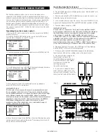
Summary of Contents for RMDS1

Page 1: ...INSTRUCTION MANUAL RMDS 1 RMDS 1 ...

Page 2: ...ease read this manual thoroughly for information on getting the greatest enjoyment from your new system Designing high quality audio products is more than just a busi ness for the people of Polk Audio it is our passion We are all dedicated to your complete satisfaction and delight Should you have any problem or question regarding this or any Polk Audio product consult your Polk Audio dealer or cal...

Page 3: ...re finished we found we had created something entirely new a no compromise sub sat surround system with all of the electronics for a high performance Dolby Digital home theatre integrated into a single complete system We call it the RM Digital Solution An Intelligent A V Pre amp Processor and High Performance Loudspeaker System With the RMDS 1 you have everything you need except sources There s no...

Page 4: ...er This plug will fit into the power outlet only one way This is a safety feature If you are unable to insert the plug fully into the outlet try reversing the plug If the plug should still fail to fit contact your electrician to replace your obsolete outlet Do not defeat the safety purpose of the polarized plug 12 Power Cord Protection Power supply cords should be routed so that they are not likel...

Page 5: ...eaving your chair Half of the world is looking for the meaning of life The other half is looking for better bass This is as good as humor gets in the audio business If you are part of the latter group we ve got the subwoofer for you The RMDS 1 subwoofer uses our patented Power Port bass venting system to deliver deep powerful bass with low distortion Your friends will be green with envy Most folks...

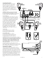
Page 6: ... 1 preamp processor to a video input on your TV 4 Connect the RMDS 1 to the subwoofer with the supplied 4 meter DB 25 cable 5 Using the supplied speaker wires connect the speakers to the speaker terminals on the back of the subwoofer Be sure to maintain correct polarity to to on all channels The wire with the black band should always be connected to the black terminal and the wire with the color b...

Page 7: ...ks will help you unify the remote control functions of the RMDS 1 and the new device Area G Multi pin Connectors on Preamp Processor and Subwoofer These may look like connectors for computer printers but they are not This is the way the 6 channels of sound get from the preamp processor to the 6 amplifiers that are built in to the subwoofer enclosure We even supply the cable Area H Speaker Connecti...

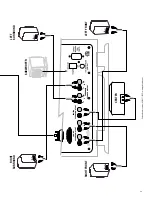
Page 8: ...O INPUTS Left CD TAPE In TAPE Rec Out DSS LD DVD VCR Rec Out VCR In ANTENNA DSS out in REMOTE CONTROL EXTENSION AC OUTLET SWITCHED 120V 60HZ 100W 0 8A AC OUTLET UNSWITCHED 120V 60HZ 100W 0 8A D I G I TA L A U D I O I N P U T S DVD LD RF Multi Room Output FM 75Ω GROUND AM VIDEO INPUTS DSS S VHS OR Standard LD DVD VCR Rec Out VCR Input Video TVout AUDIO OUT connect to subwoofer VHF UHF CABLE TV BASI...

Page 9: ...lkaudio com 9 FRONT SPEAKER OUTPUT CENTER SPEAKER OUTPUT SURROUND SPEAKER OUTPUT L R AUDIO INPUT L R SUBWOOFER RIGHT SURROUND RIGHT FRONT LEFT FRONT LEFT SURROUND CENTER CONNECTS TO PROCESSOR SPEAKER HOOK UP ...

Page 10: ...t of the DVD player and use the DVD player as an audio source for a remote room Connect either the composite video or the S video output of the DVD player to the corresponding DVD video input of the RMDS 1 Do not use both composite and S video connections If you use S video connections here you must connect your TV to the RMDS 1 preamp processor with an S video cable in order to get a picture with...

Page 11: ... DSS inputs almost all DVD players have an optical output Connect either the composite video or the S video output of the DSS receiver to the corresponding DSS video input of the RMDS 1 Do not use both composite and S video connections If you use S video connections here you must connect your TV to the RMDS 1 preamp processor with an S video cable in order to get a picture with this input Connecti...

Page 12: ...y free composite video input of your TV If you are using only S VHS S Video video inputs for your video sources and no standard composite sources just connect the VIDEO TV out to any free S video input of your TV If you want the audio from your TV to play through the system just connect its audio outputs to any unused set of analog input jacks on the RMDS 1 such as LD AUX on the front panel or Tap...

Page 13: ...ers Follow the same procedure described above to connect the rear surround speakers to the Left Surround and Right Surround speaker outputs on the subwoofer amplifier Use the 40 12M wires IMPORTANT NOTE Be careful to maintain correct polarity on all the speakers by always using the speaker wire with the color insulator for the red terminals and the black marked wire for the black terminals ON THE ...

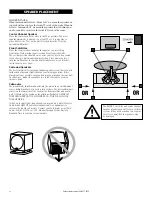
Page 14: ...est placement for surround channel speakers is on the side walls facing each other and slightly behind your listening position If this placement is not possible the speakers may be placed on the rear wall In either case mount the speakers two to four feet above a seated listener s head Subwoofer The magnetically shielded subwoofer may be placed in an entertainment center behind furniture or next t...

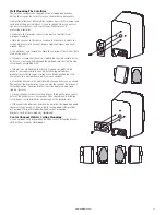
Page 15: ...crew heads protruding 1 16 If there is no stud behind the chosen location install 10 wall anchors not supplied into the wall by following wall anchor manufacturer s instructions leaving screw heads protruding 1 16 Always use two wall anchors and screws per speaker Attach the bracket to the satellite with the supplied screw as shown The angle of the bracket allows you to point the speaker toward yo...

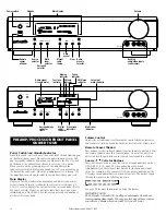
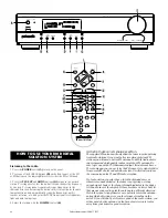
Page 16: ... position When you turn on the preamp processor the amplifiers in the subwoofer enclosure will also turn on and you will see a green glow on the base of the subwoofer When the preamp processor is turned Off the amplifiers turn off and the light in the subwoofer base glows red Main Display Displays a variety of information depending on what action was most recently taken Normally it indicates the c...

Page 17: ...ar Button When you want to clear a radio station from the list of presets select that preset station then press and hold the Clear button until CLEAR appears on the display See page 22 for more information on using this feature Presets Buttons These button select from the list of preset radio stations Pushing the button moves from lower preset numbers to the higher preset numbers Pushing the butto...

Page 18: ...r buttons M Status display N Balance set up menu selector Q Set up menu navigation buttons G Radio preset selector F Radio manual tuning D Volume Control J Radio preset scan K Audio input selector L Video input selectors P Multi room selector O Delay set up menu selector R Menu command button E Mute Loading Remote Control Batteries 1 Remove the back cover 2 Insert two AA type batteries with correc...

Page 19: ...stations Pushing the right side of the rocker button moves from lower preset numbers to the higher preset numbers Pushing the left side of the rocker button moves down through the list of preset stations See page 23 for more information on using this feature H Late Night Button This button toggles between Late Night and Normal modes In the Late Night mode the dynamic range of the signal is reduced...

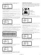
Page 20: ...n the remote to cancel this procedure Re read the Subwoofer and Speaker Connections section of this manual and correct the wiring error before returning to this procedure 10 You will see a small square indicator cursor next to the current speaker Use the directional buttons on the remote to pick up the indicator and move it to the next speaker in the array Center 11 The test tone should now come f...

Page 21: ...ctory defaults return to this on screen menu select DEFAULTS ON save and exit The factory settings will be restored Front Minus Surround Dolby Digital Pro Logic Distance feet Surround Delay Setting Surround Delay Setting 1 3 feet 5ms 15mS 4 6 feet 5ms 20mS 7 11 feet 10ms 25Ms 12 feet or more 15ms 30mS Setting Dolby Pro Logic Delay The channel delay function for Dolby Pro Logic exists for a somewha...

Page 22: ...requencies until it reaches a station at which point the TUNED and signal level indicators light and auto tuning stops 4 Adjust the volume with the VOLUME control E IMPORTANT NOTES ON FM RADIO RECEPTION The supplied FM antenna will only allow the tuner to pick up strong local radio stations If you want better reception of distant FM stations you will need a better FM antenna Your Polk Audio dealer...

Page 23: ...multaneously for more than 3 seconds CAUTION The all memory clear operation clears all memory including the volume level and surround mode memory and turns the power OFF Playing a DVD or other audio video source 1 Turn unit on by pressing POWER button A 2 Push the DVD input button J on the remote or use the SOURCE buttons on the front panel B to toggle through the sources until the display reads D...

Page 24: ...no Dolby Digital is a digital audio compression system that provides very high fidelity sound quality in either 2 or 6 channels The six channels are Left and Right front Center Left and Right rear and a Low Frequency Effects channel or 5 1 The vast majority of Dolby Digital program materials are 5 1 multi channel recordings Most DVDs have both 2 channel and 5 1 channel Dolby Digital soundtracks In...

Page 25: ...ocessor will now go back to normal operation USING MULTI ROOM FEATURE Operating from the front panel 1 Push the MULTI ROOM button on the front panel of the preamp processor 2 The red MULTI indicator will blink and the words SEL SOURCE will appear on the display 3 Push the either the or SOURCE button to select the source you would like to play in the remote room 4 A few seconds after you select the...

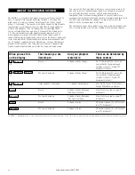
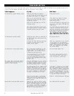
Page 26: ... a 5 1 disc and it still isn t delivering 5 1 Still no 5 1 Call your Polk dealer or Polk Audio This will definitely fix the problem Try this Make sure the subwoofer is plugged in to a live AC outlet and that the power switch on the back of the sub is set to Standby Make sure the 4 meter cable that connects preamp processor and subwoofer is firmly inserted and screwed in Make sure the MUTE light is...

Page 27: ...original purchaser only that the Preamp Processor and Amplifier in this Polk Audio Loudspeaker Product the Product will be free from defects in material and workmanship for a period of three 3 years from the date of original retail purchase from a Polk Audio Authorized Dealer Polk Audio Inc further warrants to the original purchaser only that the Loudspeaker s in this Polk Audio Product the Produc...

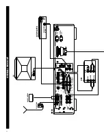
Page 28: ...APE In TAPE Rec Out DSS LD DVD VCR Rec Out VCR In ANTENNA DSS out in REMOTE CONTROL EXTENSION AC OUTLET SWITCHED 120V 60HZ 100W 0 8A AC OUTLET UNSWITCHED 120V 60HZ 100W 0 8A D I G I T A L A U D I O I N P U T S DVD LD RF Multi Room Output FM 75Ω GROUND AM VIDEO INPUTS DSS S VHS OR Standard LD DVD VCR Rec Out VCR Input Video TV out AUDIO OUT connect to subwoofer OVERALL HOOK UP ...

Page 29: ... service 800 377 7655 www polkaudio com 29 FRONT SPEAKER OUTPUT CENTER SPEAKER OUTPUT SURROUND SPEAKER OUTPUT L R AUDIO INPUT L R SUBWOOFER RIGHT SURROUND LEFT SURROUND RIGHT FRONT LEFT FRONT AUDIO INPUT L R CENTER ...

Page 30: ...utyl rubber surround Crossover design Fixed active 4th order 24dB octave low pass with amplitude shaping Cabinet Dimensions 151 2 W x 183 4 H x 191 2 D Six Channel Power Amplifier System Continuous Power Output Greater than 500 Watts into 4 Ohms all channels driven Dynamic Power Output 700 watts into 4 Ohms all channels driven Bandwidth 20Hz 22kHz Distortion 0 05 Power Requirement AC 120V 50 60Hz ...

Page 31: ...www polkaudio com 31 ...

Page 32: ...5601 METRO DRIVE BALTIMORE MARYLAND 21215 USA 410 764 5275 FAX 410 764 5266 www polkaudio com RM6608 1 ...

Reviews: