background image

◊ 

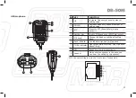
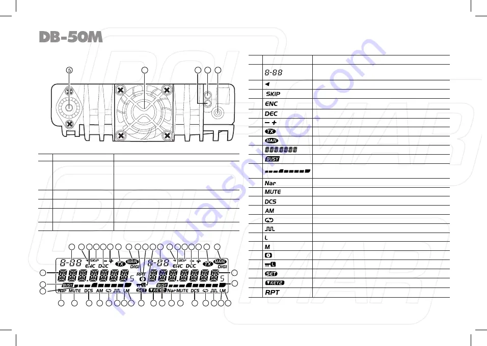
Rear panel

NO.  KEY

FUNCTION

1

Ext. Power Jack

Terminal for connecting optional cable QCC01 

for use with ignition key On/Off function. The 

radio will auto power on when car is driving. 

The radio will auto power off when car stops. 

2

Ext. Speaker Terminal Terminal for optional external speaker  SP02.

3

Not in use

4

Heatsink fan

Runs automatically when radio temperature 

rise up.

5

Antenna Connector

Connect a 50 Ω antenna

DISPLAY

NO. INDICATOR

FUNCTION

1

Displays the channel number and Menu number.

2

Appears when current channel is priority channel.

3

Appears when current channel is set Scan Skip.

4

Appears when current channel has CTCSS Encode.

5

Appears when current channel has CTCSS Decode.

6

Appears when the Offset function is ON.

7

Appears while transmitting.

8

Displays the Main channel.

9

Displays the operating frequency,channel name.

10

Displays when receiving a signal or Monitor is ON.

11

Signal strength for receiving and power level for 

transmitting.

12

Appears while in Narrow band.

13

Appears when mute has been turned ON.

14

Appears when the DCS function is ON.

15

Appears while in AM mode.

16

Not in use

17

Appears when the Compander function is ON.

18

Appears while using Low output power.

19

Appears while using Middle output power.

20

Appears while Auto power off function is ON.

21

Appears when the Key Lock function is ON.

22

Appears when press SET key.

23


Appears when choose KEY2 mode.

24


Not in use

12

4

1

3

2

1

1

10

11

11

12

12

13

13

14

14

15

16

16

21

22

17

17

18

18

19

19

20

23

24

9

8

2

5

3

4

6 7

8

2

5

3

4

6 7

9

9

Summary of Contents for DB-50M

Page 1: ...Importato e distribuito da Polmar srl Manuale d uso User s manual ricetrasmettitore DUAL BAND VHF UHF DUAL BAND VHF UHF TRANSCEIVER...

Page 2: ...trasmettitore biban da particolarmente indicato per uso veicolare in linea con la filosofia Aziendale di innovazione NOTE Prima di programmare il ricetrasmettitore leggete questo manuale poi potete im...

Page 3: ...evitare danni personali rischio d incendio o danni al ricetra smettitore vi preghiamo di osservare questi punti Non intervenite nella programmazione durante la guida di un veicolo pericoloso Questo ri...

Page 4: ...16 Regolazione livello squelch 16 Trasmettere toni DTMF 16 Commutazione potenza alta media bassa 16 Inversione di frequenza 16 Selezione larghezza di banda 16 Canale HOME 16 Canale memoria 16 Doppio a...

Page 5: ...e modalit schermo 29 Blocco canale occupato 30 TOT temporizzatore durata massima trasmissione 30 Aggancio frequenza VFO 31 Larghezza banda larga stretta 31 Retroilluminazione LCD 31 Luminosit retroill...

Page 6: ...icezione UU UV VU VV Grande schermo LCD a luminosit regolabile utile per uso notturno Ricetrasmettitore con ergonomica distribuzione dei comandi Realizzato con materiali d ottima qualit ed evoluta tec...

Page 7: ...M4X8 mm 4 Viti autofilettanti M5X8 mm Cavo programma zione USB Cavo con presa ac cendisigari Microfono da tavolo Alimentatore Staffa pannello frontale Altoparlante esterno V M HM SC N LOW LOW V M HM S...

Page 8: ...scher mati dai raggi solari 1 Installate la staffa di montaggio nel veicolo usando la minute ria in dotazione 2 Posizionate il ricetrasmettitore fissatelo con le 4 viti esagonali SEMS in dotazione Ver...

Page 9: ...te al calore 3 Per evitare rischi di corto circuito staccate il morsetto negativo della batteria poi collegate la radio 4 Verificate che la polarit sia corretta poi collegate il cavo d a limentazione...

Page 10: ...ndo si accende il quadro con la chiave posizione avvio e il tasto accensione della radio sulla posizione accesa la radio si accende automaticamente Si pu spegnere girando la chiave quadro o agendo sul...

Page 11: ...a bassa perdita anch esso d impedenza di 50 per accordarsi alla impedenza presentata dalla presa d antenna del ricetrasmettitore Accoppiando l antenna al ricetrasmettitore con discese d impedenza dive...

Page 12: ...comunicare a voce collegate il microfono in dotazione la spina a 8 poli va inserita nella presa presente frontalmente nell unit centrale Spingete fino a d aggancio Fissate la staffa microfono tramite...

Page 13: ...a potenza RF H L Premuto a lungo at tiva disattiva inversione frequenza 9 Tasto V M In modo attesa commuta tra modo me moria e VFO Premuto a lungo commuta tra larghezza di banda larga stretta 10 Tasto...

Page 14: ...Il canale corrente ha decodifica CTCSS 6 Il canale corrente ha spaziatura offset attiva 7 In trasmissione 8 Canale principale 9 Frequenza operativa etichetta canale 10 Si riceve un segnale o il monit...

Page 15: ...B Selezione banda destra sinistra come principale 6 Indicazione banda Spia banda principale 7 Spia TX RX Verde in ricezione rosso in trasmissione 8 MIC Parlare rivolti verso questo punto in trasmissio...

Page 16: ...za ha un passo di 1 MHz Immettere la frequenza tramite i tasti numerici del micro fono In modo VFO potete sintonizzare una frequenza immettendola numericamente direttamente Una immissione oltre la ban...

Page 17: ...o intervento per commutare la banda Il ricetrasmettitore si pu impostare per lavorare su 2 bande UHF o 2 VHF NOTE Ricezione In modo attesa ricevono sia la banda si nistra sia la destra Rilevato un seg...

Page 18: ...25 W VHF 10 W VHF 5 W UHF 40 W UHF 25 W UHF 10 W UHF 5 W In modo memoria questa impostazione temporanea NOTE Inversione di frequenza Si attiva disattiva in modo attesa premendo per 0 5 il tasto Quando...

Page 19: ...o premente sui tasti UP DOWN del microfono 3 Terminate la scansione premendo Esclusione canale scansione In modo memoria selezionate il ca nale con la manopola selezione poi tenete premuto per 0 5 il...

Page 20: ...il tasto a schermo appare MEN IN la copia si completata Cancellazione canale 1 In modo attesa tenete premuto il tasto finch la radio emette DU l indicazione numero canale lampeggia 2 Selezionate il c...

Page 21: ...one la spaziatura 1 Premete per richiamare il men 2 Con la manopola banda principa le selezionate il passo 02 men A schermo appare ARS 3 Entrate in impostazione premendo la manopola 4 Impostate il val...

Page 22: ...schermo appare BEEP 3 Entrate in impostazione premendo la manopola 4 Impostate il valore voluto ruotando la manopola banda principale ON cicalino attivato OFF cicalino disattivato 5 Premete la manopo...

Page 23: ...S attivi CTCSS subtoni DCS attivo DCS codice digitale 5 Premete la manopola banda principale per entrare nel men 6 Con la manopola selezione banda principale scegliete il CTCSS o il codice DCS voluto...

Page 24: ...azioni a schermo banda secondaria 1 Premete per richiamare il men 2 Con la manopola banda principa le selezionate il passo 12 men A schermo appare DSP SUB 3 Entrate in impostazione premendo la manopol...

Page 25: ...inghe codice DTMF 5 Quando avete selezionato una locazione stringa libera a schermo appare 6 Premete la manopola selezione per editare la segnalazione DTMF A schermo appare la prima posizione cursore...

Page 26: ...rnare al men Premete SQL o la manopola banda princi pale per 0 5 per registrare ed uscire Nota di chiamata Questa funzione serve ad attivare i ripetitori Si invia una nota audio ad un ripetitore in at...

Page 27: ...banda principale selezionate la modalit pre ferita KEY1 modalit normale i 4 tasti superiori hanno stessa funzio nalit dei 4 tasti inferiori KYE2 i 4 tasti rotondi sono condivisi tra le due bande Ai 4...

Page 28: ...en Premete SQL o la manopola banda principale per 0 5 per registrare ed uscire Impostazione livello squelch 1 Premete per richiamare il men 2 Con la manopola banda principa le selezionate il passo 23...

Page 29: ...chermo appare NAME C 3 Entrate in impostazione premendo la manopola 4 Tramite la manopola selezionate il carattere 5 Confermate il carattere corrente premendo la manopola sele zione si passa al caratt...

Page 30: ...le barrette 5 Premete la manopola banda princi pale o il tasto per registrare e tornare al men Premete SQL o la manopola banda principale per 0 5 per registrare ed uscire Impostazione direzione spazi...

Page 31: ...iamare il men 2 Con la manopola banda principale selezionate il passo 36 men A schermo appare SHIFT 3 Entrate in impostazione premendo la manopola 4 Impostate il valore voluto ruotando la manopola ban...

Page 32: ...disattivata Si pu sempre trasmettere anche in presenza di altri segnali 5 Premete la manopola banda principale o il tasto per regi strare e tornare al men Premete SQL o la manopola banda principale p...

Page 33: ...da principa le selezionate il passo 43 men A schermo appare WIDNAR 3 Entrate in impostazione premendo la manopola 4 Impostate il valore voluto ruotando la manopola banda prin cipale WIDE banda larga 2...

Page 34: ...inci pale per 0 5 per registrare ed uscire Funzionalit AM 1 Premete per richiamare il men 2 Con la manopola banda principa le selezionate il passo 50 men A schermo appare AM 3 Entrate in impostazione...

Page 35: ...a banda principale LOW volume cicalino basso HIGH volume cicalino alto 5 Premete la manopola banda principale o il tasto per regi strare e tornare al men Collegamento in diretta A funzione attivata il...

Page 36: ...Potete operare con il ricetrasmettitore tramite il microfono dotato di tastiera per immettere la frequenza o selezionare un canale Inviare stringhe DTMF Tenere premuto il PTT immettere la stringa DTM...

Page 37: ...a schermo appare DCS ed il codice DCS premete il tasto microfono UP DOWN per selezionare il codice DCS MHZ In modo VFO premete sul tasto cui assegnata la funzione MHz la cifra unit frequenza lampeggi...

Page 38: ...da destra mentre accendete l apparato finch a schermo appare CLONE 3 Tenete premuto il tasto banda principale SQL sia sull unit origine sia su quella destinazione della copia appare CLONE XX XX riport...

Page 39: ...ollegate il cavo ad una diversa porta USB Dovete installare il programma prima di collegare il cavo USB Prima di trasferire dati sul ricetrasmettitore dovete accenderlo Quando il ricetrasmettitore con...

Page 40: ...e con uno nuovo Schermo molto scuro Regolare la luminosit su un livello superiore Nessun audio viene riprodotto all altopar lante Squelch silenziato Diminuire il livello squelch Attivo squelch a subto...

Page 41: ...di frequenza 2 5 ppm Temperatura operativa 20 60 C Dimensioni 139 L x 40 A x 212 P mm Peso circa 1 14 kg Ricevitore banda larga banda stretta Sensibilit 12dB SINAD 0 25 V 0 35 V Risposta audio 1 3 dB...

Page 42: ...4 045 046 047 050 051 052 053 054 055 056 057 060 061 062 063 064 065 066 067 070 071 072 073 074 075 076 077 100 101 102 103 104 105 106 107 110 111 112 113 114 115 116 117 120 121 122 123 124 125 12...

Page 43: ...37 540 541 542 543 544 545 546 547 550 551 552 553 554 555 556 557 560 561 562 563 564 565 566 567 570 571 572 573 574 575 576 577 600 601 602 603 604 605 606 607 610 611 612 613 614 615 616 617 620 6...

Page 44: ......

Page 45: ...d mobile radio especially designs for drivers and it pursues company philosophy of innovation and practicality NOTE When programming the transceiver read the factory initial data firstly then rewrite...

Page 46: ...oming years The use of this equipment is submitted to license The equipment must be used on the market in conformity with the administrative obligations of the legislation in which the transceiver is...

Page 47: ...and 15 Receiving 15 Squelch Off Squelch Off Momentary 15 Transmitting 15 Shortcut operations 16 Squelch level Setup 16 Transmit DTMF signaling 16 High Mid Low Power Switch 16 Frequency Reverse 16 Band...

Page 48: ...isplay mode Setup 29 Busy Channel Lockout 30 TOT Time out timer 30 VFO Frequency Linkage 31 Wide Narrow band 31 LCD backlight 31 Keypad backlight brightness 32 Calling Record 32 AM Function 32 Automat...

Page 49: ...V VU VV for dual receive and dual output Display on a large LCD with adjustable brightness convenient for nighttime use Distribute buttons reasonably convenient for operation Adopt su perior quality m...

Page 50: ...Black screws M4X8mm 4Tapping screws M5X8mm USB Programming Cable Cigar Plug Connection Line Desktop Microphone Power supply Front Panel Bracket External Speaker V M HM SC N LOW LOW V M HM SCN SET TV S...

Page 51: ...ion that is shielded from direct sunlight 1 Install the mounting bracket in the vehicle using the supplied self tapping screws 4 pcs and flat washers 4 pcs 2 Position the transceiver then insert and t...

Page 52: ...ort circuit please cut down connection with negative of battery then connect with radio 4 Confirm the correct polarity of the connections then attach the power cable to the battery terminals red conne...

Page 53: ...lluminated while ignition key is at ACC or ON position 8 When the ignition key is turned to ACC or ON position with the radio s power switch on the unit turns on automatically and the power switch wil...

Page 54: ...low loss coaxial feed line that has a characteristic impedance of 50 to match the transceiver input impedance Coupling the antenna to the transceiver via feed lines having an impedance other than 50 r...

Page 55: ...onnect a microphone equipped with an 8 pin modular plug into the modular socket on the front of the main unit Press firmly on the plug until the locking tab clicks Attach the supplied microphone hange...

Page 56: ...urn On Off Frequency Reverse Function 9 V M Key In standby press it to switch between channel mode and VFO mode Long press it to set Wide Narrow band 10 HM Key In standby press it to switch between HO...

Page 57: ...channel has CTCSS Decode 6 Appears when the Offset function is ON 7 Appears while transmitting 8 Displays the Main channel 9 Displays the operating frequency channel name 10 Displays when receiving a...

Page 58: ...t band or right band as Main band 6 Band indicator The indicator light on for Main band 7 TX RX indicator Light green while receiving Light red while transmitting 8 MIC Speak here during transmission...

Page 59: ...turn the selector knob will increase or decrease frequency quickly by 1 MHz step Input Frequency THROUGH Microphone number key In VFO mode you can input the frequency by the microphone numeric key It...

Page 60: ...l switch the right band Receiving In standby both left band and right band are able To receive When they receive any signal the BUSY icon and signal strength icon will appear in the corresponding area...

Page 61: ...VHF 25W VHF 10W VHF 5W UHF 40W UHF 25W UHF 10W UHF 5W In channel mode this operation is for temporary use only NOTE Frequency Reverse In standby hold key for over 0 5 second to turn On Off frequency...

Page 62: ...lector knob or press microphone UP DOWN key will change the scan direction 3 Press key to exit scan Channel Scan Skip In channel mode switch selector knob to choose the channel then hold for over 0 5...

Page 63: ...y the frequency otherwise will display 4 Press key the LCD displays MEN IN channel copy completed Channel Delete 1 In standby hold key until the transceiver prompt DU and channel number flashes 2 Turn...

Page 64: ...uency The operation as following 1 Press key to enter function menu 2 Turn the Main band selector knob to choose No 02 menu The LCD displays ARS 3 Press the Main band selector knob to enter function s...

Page 65: ...n band selector knob to enter function setup 4 Switch the Main band selector knob to choose wanted value ON Turn on Beep function OFF Turn off Beep function 5 Press the Main band selector knob or key...

Page 66: ...OFF Turn off CTCSS DCS encode CTCSS Choose CTCSS encode DCS Choose DCS encode 5 Press the Main band selector knob to enter the menu 6 Switch the Main band selector knob to choose wanted CTCSS DCS code...

Page 67: ...ob to enter function setup 4 Switch the Main band selector knob to choose wanted value FREQ display sub band frequency DC IN display sub band voltage OFF turn off display for sub Band 5 Press the Main...

Page 68: ...hen press key back to DTMF menu Press PTT will transmit with selected DTMF code 06 16 total 16 group of DTMF code 5 When the selected group is empty the LCD displays 6 Press the selector knob to enter...

Page 69: ...exit Tone BURST Pilot Frequency This function uses to start repeater It needs certain intensity Pilot Frequency to start a dormant repeater As usual no need to send pilot frequency again once repeate...

Page 70: ...ode KEY1 key1 mode Normal mode the top 4 keys have same functions as the bottom 4 keys KYE2 the top 4 keypads will shared by both band And the bottom 4 key pads will be re defined 5 Press the Main ban...

Page 71: ...u Press SQL key or hold selector knob for over 0 5 second to store setup and exit Squelch Level setup 1 Press key to enter function menu 2 Turn the Main band selector knob to choose No 23 menu The LCD...

Page 72: ...in band selector knob to enter function setup 4 Switch the selector knob to choose wanted character 5 Press the selector knob to confirm current character and start edit next character after editing a...

Page 73: ...value and back to function menu Press SQL key or hold selector knob for over 0 5 second to store setup and exit OFFSET Direction setup 1 Press key to enter function menu 2 Turn the Main band selector...

Page 74: ...r knob to choose wanted value Available Offset frequency for this transceiver is 0 100 MHz 5 Press the Main band selector knob or key to store value and back to function menu Press SQL key or hold sel...

Page 75: ...ng carrier OFF Busy channel lockout is disabled Transmitting is allowed in any receiving status 5 Press the Main band selector knob or key to store value and back to function menu Press SQL key or hol...

Page 76: ...unction menu 2 Turn the Main band selector knob to choose No 43 menu The LCD displays WIDNAR 3 Press the Main band selector knob to enter function setup 4 Switch the Main band selector knob to choose...

Page 77: ...setup and exit AM Function 1 Press key to enter function menu 2 Turn the Main band selector knob to choose No 50 menu The LCD displays AM 3 Press the Main band selector knob to enter function setup 4...

Page 78: ...ue LOW BEEP volume is low HIGH BEEP volume is high 5 Press the Main band selector knob or key to store value and back to function menu TALK AROUND With this function on the transceiver will not able t...

Page 79: ...ogrammed before using this function NOTE Microphone Operation You can operate the transceiver by keypad or input desired frequency and channel through the microphone Send DTMF signaling Hold the PTT k...

Page 80: ...DOWN key to choose CTCSS encode When the LCD displays ENC DEC and CTCSS frequency press the microphone UP DOWN key to choose CTCSS decode When the LCD displays DCS and DCS code press the microphone U...

Page 81: ...2 Press and hold right band key to power on then hold this key until the LCD displays CLONE 3 Hold the Main band SQL key The Master unit and Slave unit both display CLONE XX XX stands for the data amo...

Page 82: ...in same computer the selective COM Port is different when USB cable connects with different USB port You shall install software before connecting the USB cable line Switch on transceiver before writin...

Page 83: ...fuse c Display is too dim Adjust the Dimmer to higher level d No sound comes from speaker Squelch is muted Decrease squelch level Tone or CTCSS DCS squelch is active Turn CTCSS or DCS squelch off e Ke...

Page 84: ...CTCSS DCS DTMF Frequency Stability 2 5 ppm Operating Temperature 20 60 C Dimensions 139 W x 40 H x 212 D mm Weight about 1 14 kg Receiver Wide band Narrow band Sensitivity 12dB SINAD 0 25 V 0 35 V Au...

Page 85: ...045 046 047 050 051 052 053 054 055 056 057 060 061 062 063 064 065 066 067 070 071 072 073 074 075 076 077 100 101 102 103 104 105 106 107 110 111 112 113 114 115 116 117 120 121 122 123 124 125 126...

Page 86: ...37 540 541 542 543 544 545 546 547 550 551 552 553 554 555 556 557 560 561 562 563 564 565 566 567 570 571 572 573 574 575 576 577 600 601 602 603 604 605 606 607 610 611 612 613 614 615 616 617 620 6...

Page 87: ...k that you have the correct version of this radio or the correct programming of this radio to comply with national licensing requirements L apparato pu essere utilizzato sul territorio nazionale limit...

Page 88: ...nzionale operante a condizione che l ap parecchiatura non sia stata manomessa o modificata e che l utilizzo del l apparecchiatura stessa sia avvenuta in modo conforme alle caratteristiche tecniche del...

Page 89: ...44...

Page 90: ...nd Polmar mod DB 50M is in compliance with the essential requirements and other relevant provi sions of Directive 1999 5 CE ES Por medio de la presente Polmar srl declara que el Polmar DB 50M cumple c...

Page 91: ...parte dell utente comporta l applicazione delle sanzioni amministrative di cui al dlgs n 22 1997 articolo 50 e seguenti del dlgs n 22 1997 USER INFORMATION In accordance with art 13 of the Legislativ...

Page 92: ...47...

Page 93: ...Importato e distribuito da Polmar srl info polmar radio com www polmar radio com...

Reviews: