7
https://eckstein-shop.de/
Schematic diagram for the DRV8824/DRV8825 stepper motor driver carrier.
The current sense resistors (R2 and R3) on the DRV8825 carrier are 0.100 Ω. This
schematic is also available as a downloadable pdf (196k pdf).
KEY DIFFERENCES BETWEEN THE DRV8825 AND A4988
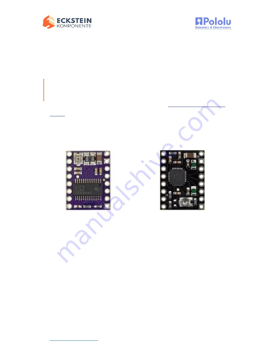
The DRV8825 carrier was designed to be as similar to our
A4988 stepper motor driver
carriers
as possible, and it can be used as a drop in replacement for the A4988 carrier
in many applications because it shares the same size, pinout, and general control
interface. There are a few differences between the two modules that should be noted,
however:
DRV8825 stepper motor
driver carrier.
The pin used to supply logic voltage to the A4988 is used as the
DRV8825’s FAULT output, since the DRV8825 does not require a logic supply (and the
A4988 does not have a fault output). Note that it is safe to connect the FAULT pin
directly to a logic supply (there is a 1.5k resistor between the IC output and the pin to
protect it), so the DRV8825 module can be used in systems designed for the A4988 that
route logic power to this pin.
The SLEEP pin on the DRV8825 is not pulled up by default like it is on the A4988, but
the carrier board does connect it to the FAULT pin through a 10k resistor. Therefore,
A4988 stepper motor driver
carrier, Black Edition (shown
with original green 50 mΩ
current sense resistors).


