1
POLOLU ROMI ENCODER PAIR KIT, 12 CPR,
3.5-18V
USER’S GUIDE
PINOUT AND INSTALLATION
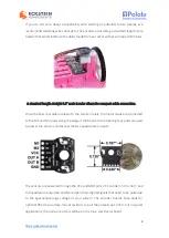
The encoder board is designed to be soldered directly to the back of the motor, with
the back shaft of the motor protruding through the hole in the middle of the circuit
board. One way to achieve good alignment between the board and the motor is to tack
down the board to one motor pin and to solder the other pin only when the board is
flat and well aligned. Be careful to avoid prolonged heating of the motor pins, which
could deform the motor case or brushes.
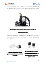
We currently have two boards that the these encoders can directly plug into: the Romi
32U4 Control Board and the Motor Driver and Power Distribution Board for Romi
Chassis. The encoder pins need to be installed pointing down toward the chassis in
order to be able to plug into this board.
The Romi Encoder can plug directly into
the Motor Driver and Power
Distribution Board for Romi Chassis.
Romi 32U4 Control Board with LCD on a
Romi chassis.


