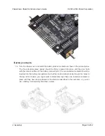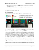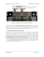
pins on the Zumo Shield will not be connected to anything. To use an I²C device on those pins, you
can connect SDA to A4 and SCL to A5 yourself by bridging across those two sets of pins in the front
expansion area.
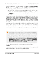
further explains the I²C lines and the jumpers connecting them to the on-
board compass module.
Depending on the Arduino model, digital pin 3 or 6 is used to control the buzzer if you
install the buzzer control jumper. If you are using an Uno, pin 6 will be available for
general-purpose I/O. If you are using a Leonardo or A-Star, pin 3 will be available if
you are not using I²C. These pins are not accessible via the front expansion, but they
can be accessed from other points on the shield and used for interfacing with additional
electronics if free. Additionally, digital pin 12 can be used for interfacing with many types
of additional electronics, especially if you are not using the shield’s user pushbutton. Pin
12 is completely free when the pushbutton is in its default, unpressed state, and it is
pulled low through a 1k resistor when the pushbutton is pressed.
3.c. Jumper settings
The Zumo shield has several jumpers that let you change the way it is connected to the Arduino, as
shown in the picture below.
Pololu Zumo Shield for Arduino User’s Guide
© 2001–2019 Pololu Corporation
3. The Zumo Shield in detail
Page 34 of 52

