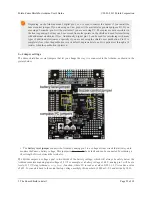
The
ZumoBuzzer library
[http://www.pololu.com/docs/0J57/6]
uses hardware PWM to play notes on the buzzer, with
digital pin 3
(OC2B) on an Arduino
Uno
or an older Arduino, or with
digital pin 6
(OC4D) on an Arduino
Leonardo
. A jumper is provided to connect the BZ input to the appropriate Arduino output, as detailed in
Section
3.c
.
Front expansion area
A number of I/O, power, and ground connections are brought to the front of the Zumo Shield to allow the mounting
of additional sensors and other components. The pinout of this front expansion area is detailed in
Section 3.b
.
3-axis compass module
The Zumo Shield includes an onboard LSM303DLHC 3-axis compass module, which can be used to sense
acceleration and magnetic field direction for advanced applications. The compass module is detailed in
Section 3.d
.
3.b. Front expansion
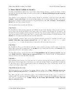
The pins in the front expansion area of the Zumo Shield are shown in the following diagram:
This diagram is also available as a downloadable PDF:
Zumo Shield front expansion pinout
[http://www.pololu.com/file/download/zumo_shield_front_expansion_pinout.pdf?file_id=0J592]
(552k pdf)
.
The front expansion makes available digital pins 2, 4, 5, and 11 and analog pins A0 through A5. It also provides
access to the two I²C pins (SDA and SCL). However, please note that the I²C pins are
not
independent pins; they are
respectively duplicates of analog pins A4 and A5 on the Uno R3, and digital pins 2 and 3 on the Leonardo. Typically,
you will only be able to use these pins for either I²C communication or general I/O, not both. Additionally, pin A1 is
used to monitor the battery voltage if you install the battery monitor jumper.
Please note that only components and connectors in the front three rows of pins can extend below the shield; the
fourth row covers the chassis and is only suitable for components mounted above the shield.
If you use an Arduino Uno R2 or an older Arduino, which lack separate I²C pins, the SDA and SCL pins on the Zumo
Shield will not be connected to anything. To use an I²C device on those pins, you can connect SDA to A4 and SCL to
A5 yourself by bridging across those two sets of pins in the front expansion area.
Section 3.c
further explains the I²C
lines and the jumpers connecting them to the onboard compass module.
Pololu Zumo Shield for Arduino User's Guide
© 2001–2013 Pololu Corporation
3. The Zumo Shield in detail
Page 24 of 38


