12
IK-E283-001E
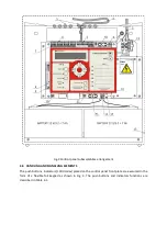
button
/delay re-enablement (switch on)– return to settled T1,
T2 times
6
Yellow
diode
Indication of disablement of alarm signalling devices
installed in L5 or L6 lines:
•
by flashing light – disablement of one line (L5 or
L6),if both were configured as alarm lines
•
by steady light – disablement of all signalling
devices (both L5 and L6 alarm lines, or one alarm
lines if only one was configured as alarm line
Push
button
Disablement/ re-enablement of signalling devices
installed in L5 or L6 line
7
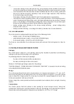
Push
button
In the alarm mode:
•
acknowledgement of receipt of fire alarm by
personnel and the control panel internal
acoustic signalling device silencing
•
change of alarm outputs activation delay time
intended for fire danger recognition from T1 to
T2 (in the case of the two-stage alarm variant))
In the fault mode:
•
fault acknowledgement and the control panel
internal acoustic signalling device silencing
8
Push
button
Reset of alarm mode of the control panel and detectors
in detection lines
9
Zone field
Red
diodes
Indication of alarm mode of the zone (line) No. 1, 2, 3, 4,
5, 6
•
the first zone where the alarm mode occurred is
signalled by flashing light, afterwards by steady
light
•
zone fields enable text description of the fire
zone (from the bottom: a slot to insert a label
with description)
10
Green
diode
Indication of the control panel operation powered from
230 V/50 Hz mains or reserve battery;
11
Yellow
diode
Program memory fault, RAM memory fault or
configuration fault signalling.
12
LCD
display
Displaying the information as per description in p. 4.8
13
Push
button
Main push button for the control panel menu handling.
•
‘short’ pressing < 1 s – entering the submenu
one level down,
•
‘long’ pressing > 1 s – return to the submenu
one level up.
14
Push
buttons
Push buttons for function selection, ‘scrolling’ events or
faults, selected parameter change.
Push
buttons
Parameter selection push buttons (moving cursor to the
left-right)


