IK-E339-001E
19
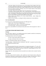
the control panel is damaged. It is necessary to switch the control panel power supply off and call the
service personnel.
In the fault mode, the PK8 general fault relay is released.
5.4 DISABLEMENT MODE
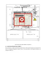
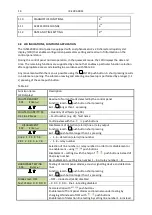
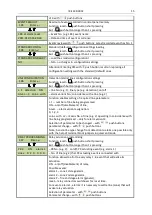
The disablement mode is signalled by the control panel by the yellow DISABLEMENT (3) diode. Any
disablement and re-enablement (and the disabled outputs readout) is possible after entering at least
2
nd
access level code and with the DISABLEMENT (3) quick access push button or using the F.03
DISABLEMENT function. The disablement concerns all inputs/outputs/L1 ÷ L6 line outputs and PK1 ÷
PK8 relay outputs. The disabled detection lines are inactive, they do not report any fault or alarm,
and relay and alarm outputs are switched off. The yellow DISABLEMENT (3) diode stops the
disablement mode indication when all disablements are removed.
5.5 TESTING MODE
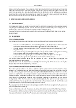
The control panel allows for testing fire warning devices in detection lines by actuating them with
e.g. fire factor imitators. Switching a zone (line) into the testing mode is possible after entering at
least 2
nd
access level code. Testing is executed utilising the F.04 HARDWARE TESTING function, which
is available immediately after pressing the TESTING push button. During the testing mode, the
control panel does not indicate a fire alarm and does not actuates any outputs linked with it. The test
alarm indication is limited to the red diode flashes in the zone field of the number consistent with the
detection line being tested. The signalling duration time is equal to several seconds, it begins at the
moment when a test alarm is reported by the detector and control panel and is finished with an
automatic reset.
The F.04 HARDWARE TESTING function enables also an efficiency inspection of all diodes located on
the control panel front side and internal acoustic signalling device.
In general, the testing mode is indicated by the TESTING (4) diode when at least one line is switched
over into the testing mode.
6 POWER SUPPLY
6.1. BASIC POWER SUPPLY
The control panel basic power supply source is 230 V/50 Hz mains. A voltage alteration 10 %
and -15 % range does not influence the control panel proper operation. The control panel internal
power supply device has the general current efficiency at 1.5 A, which is used for the control panel
and charging circuits power supply; 0.4 A load is reserved for auxiliary external devices.
6.2. RESERVE POWER SUPPLY
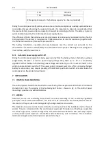
In case of mains voltage outage, the control panel is supplied from a reserve battery cluster of 24 V
nominal voltage and 3.2 ÷ 7 Ah capacity. A switch-over from the main power supply to the reserve
one is carried out automatically, without any break in power supply. The approximate control panel
operation time when it is supplied from the batteries only at the full lines load (in the quiescent
mode and + 0.5 h in the alarm mode), with no current draw from the external device power supply
output, is presented in Table 6.1 for various battery capacities.
Table 6.1
Battery capacity
Approximate control panel
operation time
3.2 Ah
47 hours


