6
ID-E339-001GB
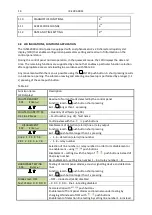
Table 2.2
Item
Description
Remarks
1
2
3
4
5
6
12 V/3.2 Ah ÷7 Ah battery
Fire detectors
Detector bases
Manual call points
WZ-31 additional indicator
Signalling devices
two pcs required for control panel
according to Appendix A
acc. to particular detector manual
according to Appendix A
according to offer
Table 2.3
Item
Part description
Quantity
1
2
3
F1 melt fuse F630L250
F2 melt fuse F500L250
F3 melt fuse T3,15L250
1 pc
1 pc
1 pc
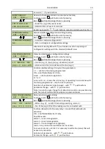
3 TECHNICAL SPECIFICATIONS
GENERAL PARAMETERS
Overall dimensions L x H x G
Mass (without batteries)
Ingress protection
Operation temperature range
Allowable operation relative humidity
Transportation temperature range
311 x 337 x 81 mm
< 4kg
IP 30
-5 °C ÷ +40 °C
95 % at +40 °C
-25 °C ÷ +55 °C
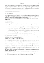
POWER SUPPLY
Basic power supply:
−
−
−
−
mains voltage
−
−
−
−
max. power draw from mains
Reserve power supply:
−
−
−
−
2 batteries, dim.: 151/65/98 (L/W/H)
−
−
−
−
reserve power supply time
−
−
−
−
battery charging current, max.
−
−
−
−
maximum battery internal resistance (together
with connecting cables and clamps)
Battery current consumption:
−
−
−
−
in quiescent mode, at max. line load
−
−
−
−
in alarm mode, max.
External devices power supply voltage
Admissible current draw from external devices power
supply output, max.
230 V + 10 % - 15 % 50 Hz
0.5 A
2 x 12 V/7 Ah (optionally 3.2 Ah, 5 Ah)
72 h
0.6 A
2 Ω
55 mA
500 mA
24 V= ±15 %
400 mA
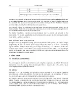
DETECTION LINES
Number of detection lines
Detection line resistance, max.
Number of detectors installed in a detection line, max.
Number of manual call points in a detection line, max.
4 ÷ 6 (depending on configuration)
2 x 100 Ω
32
10


