8
ID-E339-001GB
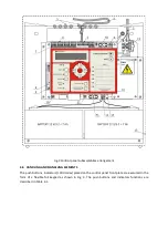
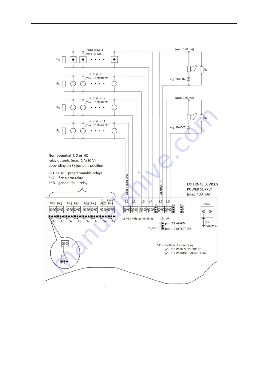
4.2 OVERALL DIAGRAM
Fig. 1 Overall diagram
4.3 CONTROL PANEL GENERAL DESCRIPTION
The control panel is intended for wall mounting. The front side is made in the form of a metal cover
plate with a rectangular window in which all handling and signalling elements are located as well as a
liquid crystal display. The cover plate can be removed after unfastening 4 screws. Cable bushings are
located in the casing upper part and they are intended to introduce alarm installation wires and
mains power supply conductors. Some space is also provided there to place spare cables. The


