ID-E339-001GB
9
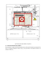
following elements are located inside the cabinet on the printed board edge: wire connectors, restart
push button, battery connection push button, configuration jumpers and USB port of the event
recorder. The control panel general view and dimensions are shown in Fig. 4.
4.4 CONTROL PANEL GENERAL OPERATION PRINCIPLE
The IGNIS 2040 is a conventional (non-addressable) control panel that interoperates with fire
detectors installed in two-core detection lines terminated with end-of-line resistors. The device
indicates a fire alarm or fault with a detection line accuracy.
The control panel processor continuously analyses all necessary information received from the
detection lines, monitors handling element status, controls optical and acoustic signalling and
controls output circuit relays. It supervises the basic and reserve power supply circuits advising
possible faults.
4.5 MODULE ARRANGEMENT
The IGNIS 2040 control panel module arrangement is shown on Fig. 2.
1.
Connection clamps for installation conductor screens.
2.
Example of detection line wire introduction and connection.
3.
Example of power supply line wire connection.
4.
Relay outputs connector (detachable from the board).
5.
Detection lines connector (detachable from the board).
6.
External devices 24 V power supply connector.
7.
Configuration jumpers:
•
S1…S8 – relay contacts configuration as closed or open,
•
S9, S10 – L5 and L6 lines function setting as detection or alarm line,
•
S11 – earth fault monitoring disconnection,
•
S12 – input filters connection with casing.
8.
USB connector.
9.
S15 jumper – default (factory) access codes restoration.
10.
‘Restart’ push button.
11.
‘wł. aku’ push button – restart of the control panel power supplied by battery cluster only.
12.
24 V reserve power supply connector (battery cluster 2 x 12 V).
13.
Potentiometer to adjust the battery buffering voltage.
14.
Slot to insert a list of fire zone descriptions.
15.
Control panel cover plate.
F1 – Battery circuit fuse - 630mA F.
F2 – External devices power supply circuit fuse - 500mA F.
F3 – Mains power supply fuse - 3,15A T.


