background image


MRR-7 Keypad    -    IMR-2 Interface


———————————————————————————— 


Maryland  USA  (410) 761-4000   -    www.polyplanar.com 


poly-planar


Waterproof Marine Audio 


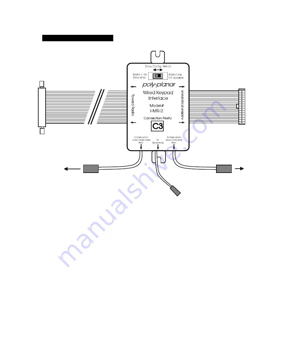
(figure 3) IMR-2 Interface 


IMR-2 CONNECTIONS 

[21] -  Zone Configuration Switch 
[22] - 

Audio Expansion Port™ Connector toward Radio (input) 

[23] - 

Audio Expansion Port™ Connector for additional expansion 

[24] -  Connector for remote in front speaker zone (or main zone) 
[25] -  Connector for remote in rear speaker zone (or secondary Zone amp) 
[26] -  Intercom audio output for Zone Amp connection 


INSTALLATION INSTRUCTIONS 


Connecting to the Audio Center:


1)  Gain access to the rear side of the Poly-Planar Audio Center. 

2)  Be sure to remove power from the Audio Center.  This is important to 

avoid damage during connection.  

3)  You  may  already  have  other  Expansion  modules  connected  to  your 

Poly-Planar  Audio  Center.    Each  Expansion  Module  is  assigned  a 

To MRR-7  

To MRR-7  

[21] 

[22] 

[23] 

[24] 

[25] 

[26] 

Summary of Contents for IMR-2

Page 1: ...e integrated microphone allows for clear communication between zones MRR 7 Remote Keypad Intercom features Waterproof design for inside or outside mounting Backlight key illumination Small size and easy to mount Available in white or black color Can be used up to 60 feet from Audio Center with optional extension cables Integrated microphone for use as intercom between boat helm and cabin or betwee...

Page 2: ...e button 15 MiniDin cable 8 pin 3 Volume UP increase 16 Microphone volume control 4 Volume DOWN decrease 17 Volume control mode switch 5 Tune seek UP CD next trk 6 Tune seek DOWN CD prev trk 7 Source select 8 Next Disc CD Changer mode 9 Band radio tuner FM 1 2 3 AM 1 2 10 Mute 11 Auto set station memory preset scan 12 Power on off 13 Sensor for IR remote control INTERCOM MIC SOURCE VOLUME TUNE DIS...

Page 3: ...ont speaker zone or main zone 25 Connector for remote in rear speaker zone or secondary Zone amp 26 Intercom audio output for Zone Amp connection INSTALLATION INSTRUCTIONS Connecting to the Audio Center 1 Gain access to the rear side of the Poly Planar Audio Center 2 Be sure to remove power from the Audio Center This is important to avoid damage during connection 3 You may already have other Expan...

Page 4: ...f the devices is important to insure proper functioning of all devices If the IMR 2 is your only expansion device then it can connect directly to the Audio Center 4 Connect the IMR 2 to the 26 pin ribbon cable in the proper location making sure that the ears on the locking 26 pin connector are latched and the blue protective tape is removed from any connectors that need to be used 5 Re connect pow...

Page 5: ...the left position b Keypad Intercoms plugged into connector 25 will broadcast into the Audio Center rear speakers or into the Zone Amplifier if present c Keypad Intercoms plugged into connector 24 will broadcast into the Audio Center front speakers or into Audio Center front AND rear speakers if the Zone Configuration switch is set to the left d 2 5mm Stereo Connector 26 provides intercom signal t...

Page 6: ...th cabin mounted Audio Center 4 speakers remote control 1 way intercom Visit www polyplanar com for complete system configuration information IN TE R C O M M I C S O U R C E V O LU M E T U N E DI S C B A N D M U TE A U T O P O W E R po ly pl an ar FM I IO 4 9 PI Helm Zone Cabin Zone IMR 2 Rear channel speakers Front channel speakers Audio Center MRR 7 ...

Page 7: ...e Switch 17 and a rotary Mic Volume control 16 on the rear panel refer to figure 1 Before the MRR 7 is permanently mounted please follow the steps below IN TE R C O M M I C S O U R C E V O LU M E T U N E DI S C B A N D M U TE A U T O P O W E R po ly pl an ar FM I IO 4 9 PI Helm Zone Cabin Zone IMR 2 Rear channel speakers Front channel speakers Audio Center MRR 7 MRR 7 IN TE R C O M M I C S O U R C...

Page 8: ...o insure that the level is adequate If the sensitivity is too high then there may be a chance of feedback or howling If the sensitivity is too low then the signal may not be loud enough to overcome engine and cabin noise For best results follow the steps below i Make all connections as described in previous section ii Verify that the system is functioning as desired Test volume buttons and interco...

Page 9: ...fore cutting the hole You will need access to the back side of the mounting surface in order to attach and tighten the mounting hardware for the MRR 7 see figure 7 Do not over tighten the mounting nut a The secondary nut on the mounting stud should be adjusted to allow the main nut to tighten against the bracket without putting excess pull on the stud of the MRR 7 b In the case of a thick mounting...

Page 10: ...affect the Audio Center as desired a Be sure that the Volume control mode switch 17 is slid toward the Radio position right looking at rear of unit 13 MRR 7 Volume control buttons do not affect the Zone Amplifier as desired a Be sure that the Volume control mode switch 17 is slid toward the Zone Amp position left looking at rear of unit b Be sure that the Zone Amplifier is connected to it s corres...

Page 11: ...e intercom is intended for use more similar to a walkie talkie than a telephone 17 There is noticeable hum or excessive noise when intercom is in use a Be sure that the cables running to the MRR 7 are not routed alone with high current vehicle wiring such as ignition or battery wires b If there are excessive engine vibrations present in the panel upon which the Intercom is mounted this may degrade...

Reviews: